3D Scanner
How to Measure Hole Positions Effortlessly
Key Takeaways
- Hole measurement is complex. Accurately measuring holes requires capturing multiple data points, with hole angle, depth, and position adding further difficulty.
- Traditional tools have limitations. Pitch calipers struggle with holes at varying heights and depths, while CMMs require time-consuming re-fixturing and stylus changes.
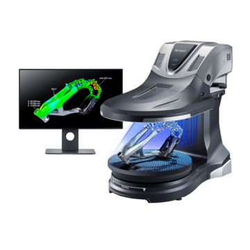
- 3D scanners simplify the process. The KEYENCE VL Series scans a full part in minutes, eliminating re-fixturing and enabling virtual cross-sections and automatic CAD comparison.
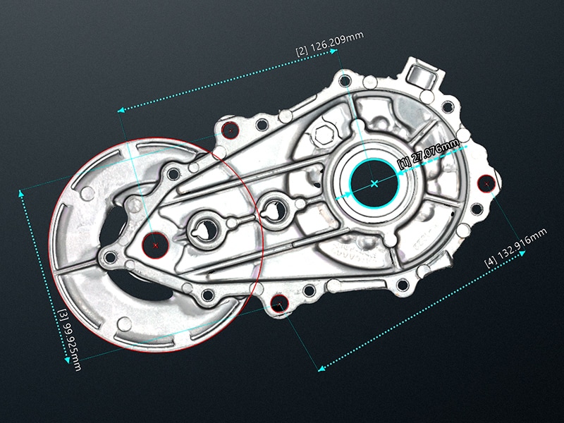
A hole in machining is a cylindrical cavity made in a part or die. To measure a hole, you often need the diameter and depth, thread inner diameter and pitch for threaded holes, and the center-to-center spacing for multiple holes.
Collecting those measurements can be more troublesome than it seems. This article covers basic hole types and measurement methods, describes typical problems with hole position measurement, and explains practical solutions. It also introduces how the KEYENCE VL Series 3D Scanner CMM can make hole position measurement easier.
What is "Hole-Making" in Machining?
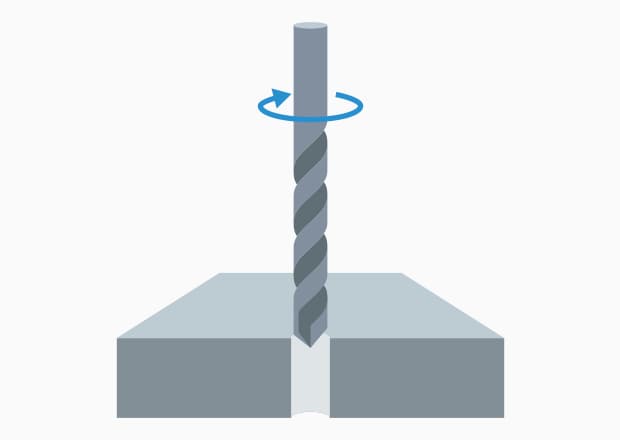
Hole making is a machining process that creates cylindrical holes in a part or material using cutting tools. This work is performed on machines such as drilling machines, lathes, and machining centers, using tools like drills, taps, and reamers. Depending on the requirements of the part, hole making can involve a single operation or a series of steps carried out in sequence to achieve the desired size, shape, and finish.
Typical operations include shallow drilling, deep drilling, and counterboring to enlarge existing holes. Additional steps such as reaming, threading, and spot facing are performed as needed to meet specific design requirements.
Types of Hole-Making
Center Drilling
Center drilling is typically the first step in the hole-making process. It creates a small, precise guide hole that helps position the drill accurately before the main hole is made. Without this step, the drill can wander or slip across the surface, leading to misplaced holes.
Drilling
Once the center hole is established, a pilot hole is drilled. If tight tolerances are not required, the process may end here, leaving what is known as a drilled hole. For larger holes, the pilot hole is gradually enlarged using a borer or end mill to reach the final diameter.
Reaming
Reaming is performed after drilling when a higher degree of accuracy is needed. A reamer is passed through the drilled hole to remove a small amount of material, smoothing the inner surface and bringing the diameter within tight tolerances.
Tapping
Tapping is the process of cutting internal threads into a drilled hole so that a bolt or screw can be fastened into it. A specialized tool called a tap is used to cut the thread pattern, and the depth and pitch of the threads must match the intended fastener.
Spot Facing
Spot facing creates a shallow, flat recess around the opening of a hole. This ensures the bolt head or washer sits flush against the surface, allowing it to tighten evenly. It is especially important on rough, curved, or angled surfaces where an uneven seating could compromise the integrity of the fastened joint.
Hole Orientation and Angle
Holes can be drilled in a variety of orientations, including straight down, at an angle, from the side, or on an inclined surface. While straightforward vertical drilling is relatively simple, angled and side drilling present unique challenges. When a drill meets a surface at an angle, the workpiece pushes back unevenly, causing the drill to deflect and the hole to be placed inaccurately.
To prevent this, there are two common approaches. The first is to use an end mill or flat drill to create a small spot face, giving the primary drill a flat, perpendicular surface to start from. The second is to use a center drill to establish a guide hole first, keeping the drill on target as it begins cutting. Both methods help ensure the hole ends up in the correct position, even on difficult surfaces.
Notation of Hole Pitch and Pitch Distance Measurement
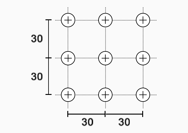
When multiple holes are drilled, the "pitch distance" (center-to-center distance) may be specified on the drawing. For example, if "30" is written as shown in the figure, it means "drill holes with a pitch of 30 mm."

19: Number of pitch intervals — not the number of holes (note: this is often mistaken) 30: Hole pitch distance (mm) 570: Total distance
For example, if a drawing shows a notation like "570 (P30×19)" or "19×30 (=570)", it means: "Drill holes at 30 mm pitch intervals. The number of pitch intervals is 19. The total length of the pitch intervals is 570 mm." A common misunderstanding is that the number "19" refers to the number of holes; in fact it denotes the number of pitch intervals. The number of pitch intervals equals the number of holes minus one, so in this case the number of holes to be drilled is 20.
Challenges in Conventional Hole Position Measurement
Machined parts can contain many different types of holes, each with its own accuracy requirements specified by tolerances on engineering drawings. Verifying that these holes meet specifications means checking a wide range of measurement points, including hole size and depth, counterbore step dimensions, and thread geometry for tapped holes. Depending on the complexity of the part, this can quickly become a time-consuming and difficult process.
Challenges of Hole Position Measurement with Pitch Calipers
Pitch calipers are a specialized tool designed to measure the center-to-center distance between holes. Their jaws fit directly into round holes, allowing for a more accurate pitch measurement than standard calipers. However, their usefulness is limited in certain situations. They perform well when all holes are on the same plane, but struggle when holes are located at different heights. Deep holes also pose a problem, as the jaws may not reach far enough to seat properly at the bottom.
Because pitch calipers are operated by hand, measurement results can vary between operators and techniques, making it difficult to ensure consistent, repeatable readings.
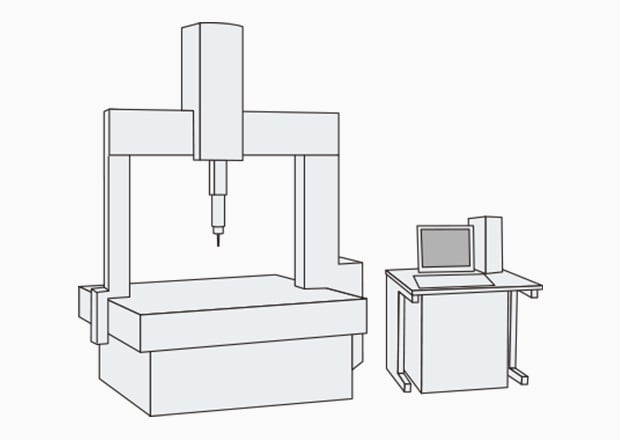
Challenges of Hole Position Measurement with a CMM
A coordinate measuring machine uses a probe to collect precise coordinate data, making it capable of measuring dimensions, positions, contours, and GD&T characteristics. Unlike pitch calipers, CMMs can handle holes at varying heights and across multiple planes.
However, they come with their own set of challenges. Angled or horizontal holes often require the part to be repositioned on the stage, and deep or unusually sized holes may require swapping probes. These steps add significant setup time and slow down the overall measurement process.
Solutions for Effortless Hole Position Measurement
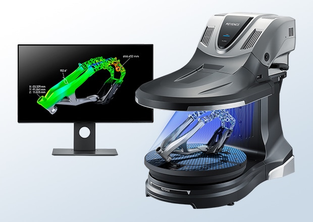
Hole position inspection can be challenging or impossible depending on hole location, size, and depth. The KEYENCE VL Series 3D Scanner CMM solves this.
The system completes a high-accuracy 360° scan on the stage in minutes and returns fast, accurate hole positions. It beats pitch calipers for speed and consistency, and, unlike typical CMMs, it captures all holes without moving or re-fixturing the part.
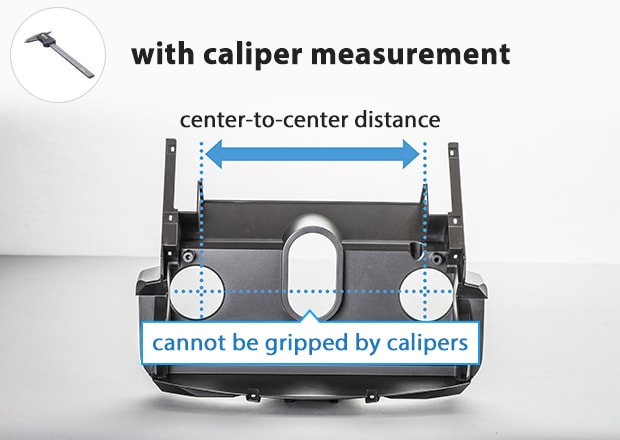
Advantage 1: Measure Locations and Shapes That Were Previously Difficult to Capture
Traditional measurement tools each come with their own limitations. Standard calipers cannot locate a hole center, making pitch measurement impossible. Pitch calipers improve on this but fall short when holes are at different heights.
The KEYENCE VL Series 3D Scanner CMM solves these problems by capturing full 3D data. Once the scan is complete, any hole position or shape can be measured accurately with just a few clicks, regardless of its location, depth, or orientation.
Advantage 2: Automatically Convert Scanned Data to CAD and Compare Against Drawings
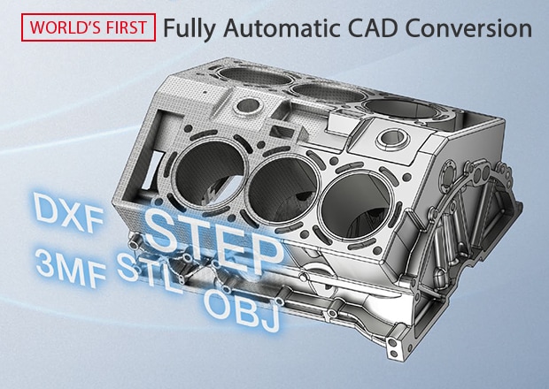
The VL Series automatically converts scan data into CAD data. Once a 3D CAD model is imported into the software, it is compared directly against the scanned data to identify any differences between the intended design and the physical part. Deviations are clearly highlighted, allowing issues to be spotted and addressed quickly without the need for lengthy manual analysis.
Advantage 3: Measure Cross-Sections Without Cutting the Sample
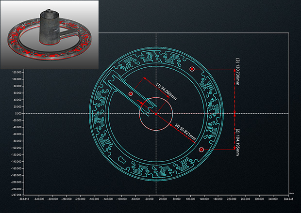
Conventional methods only measure the outer surface. The KEYENCE VL Series 3D Scanner CMM can create cross sections from the scan data without damaging the part, letting you measure and analyze details at any point.
You can choose any reference plane and “cut” the 3D model in any direction, which makes checking hole pitch at different heights easy.
Advantage 4: Measure Hole Positions in Recessed or Hard-to-Reach Locations
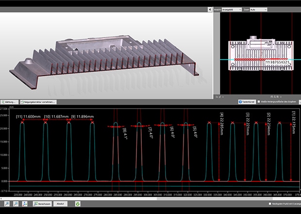
As discussed in the previous section, the VL Series can generate virtual cross-sections directly from scan data. This capability extends to measuring features that would otherwise be difficult or impossible to access with traditional tools. Deep bore shapes, spot face profiles, and tapped thread geometry can all be measured accurately without the need to reorient the part or use specialized probes. What was once a time-consuming challenge becomes a straightforward step in the measurement process.
Easy Hole Position Measurement: Achieve Time Savings and Efficiency with a 3D Scanner
Stop struggling with pitch calipers and complex CMM setups. The KEYENCE VL Series 3D Scanner CMM captures the whole part and makes hole position checks fast and easy.
- A full 360°-degree scan can be completed in minutes, cutting measurement time.
- Hole positions are measured from 3D data, so location, angle, or hole shape do not affect the result.
- No repeated reorientation of the part is required, reducing setup time.
- Scanned data is automatically converted to CAD for easy comparison with imported 3D models.
- Hole locations can be measured from a virtual cross section, improving accuracy on otherwise hard to reach features.