Measurement Sensors
Measurement Sensors
Non-contact, high precision laser distance sensors, position sensors and measurement sensors.
Measurement sensors are everywhere; they’re in the smartphone you’re holding and in the satellites orbiting our planet.
Lineup
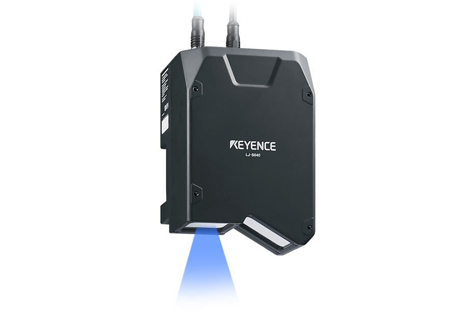
Laser Profiler / 3D Laser Snapshot Sensor
KEYENCE America's 2D/3D Laser Profile Scanners and 3D Laser Snapshot Sensor are perfect for measuring height, step height, area, angle, radius, point-to-point, point-to-line, and more.
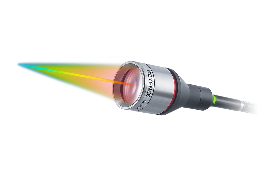
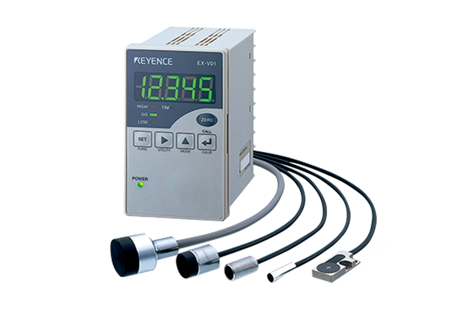
Laser Displacement Sensors
KEYENCE America's Laser Displacement Distance Sensors are single-point sensors for measuring distance, position, or thickness with speed and precision.
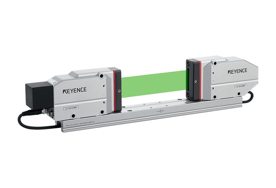
Optical Micrometer / Laser Micrometer
KEYENCE America's 1D and 2D Laser Scan micrometers and optical micrometers gauge diameter, pitch, width angle roundness, position, and radius.
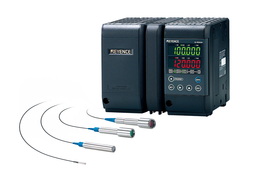
Spectral Interference Displacement Sensor
KEYENCE America's Spectral Interference Displacement Sensor measures the thickness of thin films, wafers, and other spectral targets with nanometer resolution.
Inductive Displacement Sensors
High-speed measurements of distance, runout, thickness, positioning, and eccentricity of metal targets. Inductive displacement sensors are used for measuring the changes in an object’s position through the principle of electromagnetic induction.
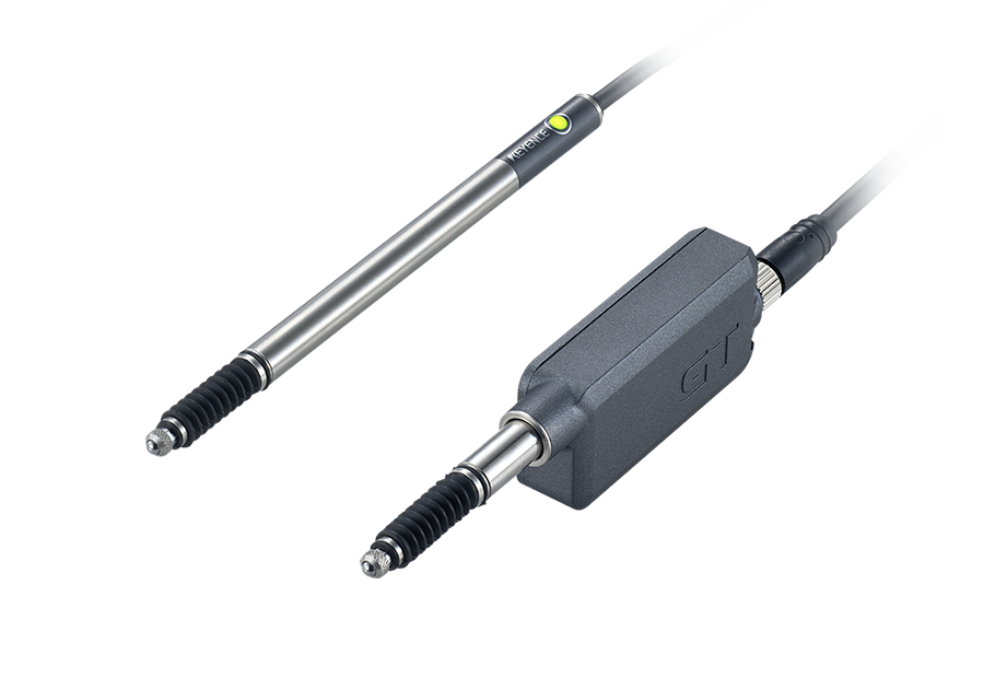
LVDT / Contact Displacement Sensors (Probes)
High precision and highly durable detection with up to 0.1-micron resolution. Connect multiple units for calculation or comparison. Linear Variable Distance Transducers, more commonly known as LVDT or contact displacement sensors, are devices used to measure the linear position of an object being touched. They’re fundamentally different from non-contact measurement sensors, as they typically require physical contact with the object or surface whose displacement is being scanned or measured.
Measuring sensors is a generic term describing various devices used to conduct measurements of physical properties, such as temperature, force, pressure, pH value, liquid level, or, in our case, an object’s position. As such, measuring sensors have become an important element of modern automation due to their capabilities to detect many different physically quantifiable properties—and even some non-quantifiable ones, like color.
In other words, these devices measure and detect displacement in physical quantities and convert them into electrical signals, which are then transmitted for data collection and processing. The methodology used in measuring and detection differs from one sensor type to the other, as some sensors rely on the physical displacement of the sensing probes, while others calculate the changes in physical properties through light interference.
Position Sensors
Position sensors detect the position of an object which has the potential to move, rotate, vibrate, etc, making them a crucial component in automation, control systems, and robotics.
Measurement Sensors
Measurement sensors comprise a rather broad category of sensors used to determine a particular value for which they have been designed and calibrated. Their applications span across numerous industries.
The rise of automated measurement is associated with the increasing demands and challenges in modern industries and research and development. Automated measurement was developed as a means of countering manual measurements done by humans relying on error-prone tools, which are prone to inconsistencies. These crude methodologies, while capable of great precision, are often time-consuming and hinder modern production.
Fortunately, automated measurement is capable of achieving incredibly high levels of precision and repeatability, which translates into more consistent quality, a significantly higher throughput, and reduced labor costs. Given how we live in the digital age, most automated measurement systems now ship with integrated software that collects, analyzes, stores, and manages said data, providing better quality control and regulatory compliance.
Measurement Sensors Applications
Thickness and Width Measurement
Learn more about width and thickness measurement with KEYENCE, including the basic principles, instruments, and methods of measuring width and thickness.
Step Height Measurement
When choosing deflection measurement sensors, consider both accuracy and speed because the sensor needs to be responsive enough to capture the change.
Inner and Outer Diameter Measurement
Learn more about Inner & Outer Diameter Measurement with KEYENCE, including the basic principles, instruments, and methods of ID/OD measurement.
Measuring Angles
Learn more about measuring angles within KEYENCE's resources, including the basic principles, instruments, and methods of angle measurement.
Meandering/Edge Measurement
Expert guidance in selecting the right solution for meandering & edge measurement. Find the measurement tools & sensors for your applications.
Positioning and Stroke Length Measurement
Learn more about stroke length and positioning measurement with KEYENCE, including the basic principles, instruments, and methods of measuring stroke and positioning.
Vibration and Runout Measurement
Learn more about vibration and runout measurement with KEYENCE, including the basic principles, instruments, and methods of measuring vibration and runout.
Deflection Measurement
When choosing deflection measurement sensors, consider both accuracy and speed because the sensor needs to be responsive enough to capture the change.
Measuring Eccentricity
When choosing eccentricity measurement sensors, consider both accuracy and speed because the sensor needs to be responsive enough to capture the change.
Profile and Shape Measurement
Learn more about profile and shape measurement with KEYENCE, including the basic principles, instruments, and methods of measuring shape and profile.
2D Profile Measurement
Learn more about 2D Profile Measurement within KEYENCE's resources, including the basic principles, instruments, and methods of 2D measurement.
3D Profile Measurement
Learn more about 3D Profile Measurement within KEYENCE's resources, including the basic principles, instruments, and methods of 3D measurement.
3D Inspection and Measurement
Learn more about 3D inspection & measurement with KEYENCE, including the basic principles, instruments, and methods of 3D inspection & measurement.
Flatness and Warpage Measurement
Learn more about flatness and warpage measurement with KEYENCE, including the basic principles, instruments, and methods of measuring flatness and warpage.
Gap/Clearance Measurement
KEYENCE has multiple sensors that can perform gap and clearance measurements. Find expert guidance in selecting the perfect system.
