Measuring Wood Shape to Increase Yield Rate: From Log Profiles to Finished Thickness
Each piece of wood has a different shape, and colors and knots vary. Capturing the shape with height data enables everything from sawing optimization to full-length thickness management.
Three Reasons Why Wood Shape Measurement Determines Yield Rate and Quality
Because the ratio of material costs is high, measurement directly leads to profit.
Sawing Cannot Be Optimized Without Knowing the Shape of the Log
Logs differ from one to another in diameter, curvature, and taper. If logs are sawed into standard shapes without understanding their geometry, products that should have been obtained cannot be produced, increasing waste. By continuously acquiring cross-sectional profiles, the most valuable sawing pattern can be determined for each log. In processes with a high ratio of material costs, a change in yield rate of just a few percent directly impacts profitability.
Variations in Finished Thickness Lead to Defects in Subsequent Processes
In planer finishing and engineered wood manufacturing, variations in thickness lead to bonding and assembly defects. For products with multiple layers of laminas, such as glulam and CLT (cross-laminated timber), variations in a single sheet accumulate and cause the overall dimensions to fall out of specification. Since sample inspection cannot capture variations along the entire length, a system is required to measure the thickness of all products along their entire length while they are running.
Knots, Color Variation, and Rough Surfaces Make Inspection Using Gray-Scale Images Difficult
The color of wood varies greatly due to knots and vessels, and there are also variations in the shading of the wood grain. In inspections that judge based on color or brightness, the shading of the wood grain may be misidentified as a defect, or conversely, depressions may be overlooked. By capturing height as a physical quantity, it is less affected by color variation, allowing for the evaluation of shape defects such as depressions and cracks. Defects that are distinguished by color, such as knots, are inspected using gray-scale images that can be acquired simultaneously with height images.
Four Measurement Points on a Lumber Processing Line
The purpose of measurement changes between the sawing process (lumber) and the finishing process (planer).
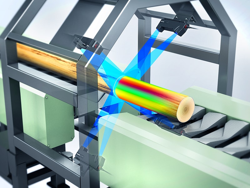
- 1 Acquiring log profiles – Process ①. Continuously acquire the cross-sectional shape of logs to understand diameter, curvature, and taper. This serves as the starting point for yield rate optimization as a basis for sawing decisions.
- 2 Understanding knots/defects and grading – Process ②. Shape defects such as depressions and cracks are captured with height data, and knots are captured with gray-scale images that can be acquired simultaneously. This makes it difficult to misidentify color variations in wood grain or vessels as defects.
- 3 Measuring finished shapes – Process ③. Measure the cross-sectional shape of tongues and grooves after processing using 3D data to quantify steps, widths, and angles. Because it is captured with height data, it is less affected by color variations in the wood.
- 4 Full-length thickness management – Process ④. Measure the thickness along the entire length based on the roller. Variations in the width direction can also be understood, leading to the management of laminated products such as glulam and CLT.
Comparison of Methods for Measuring Wood Shape and Thickness
Differences in methods appear under conditions such as color variation, rough surfaces, and total length measurement.
| Management items / Conditions | Laser triangulation method (LJ-X8000 Series) |
2D vision sensor (Gray-scale/planar inspection) |
Contact roller gauge | Sample inspection + calipers |
|---|---|---|---|---|
① Log profile (diameter/curvature) |
Laser triangulation method (LJ-X8000 Series)
◎ Continuous acquisition of cross-sectional shapes
|
2D vision sensor (Gray-scale/planar inspection)
△ Profile only
|
Contact roller gauge
× Cannot measure
|
Sample inspection + calipers
△ Limited to a few points
|
② Knot/defect detection |
Laser triangulation method (LJ-X8000 Series)
◎ Shape defects are detected by height, and knots are detected by gray-scale images
|
2D vision sensor (Gray-scale/planar inspection)
△ Wood grain is easily misidentified as defects
|
Contact roller gauge
× Cannot detect
|
Sample inspection + calipers
× Cannot detect
|
③ Finished shape (tongue and groove) |
Laser triangulation method (LJ-X8000 Series)
◎ Calculates step, width, and angle from the cross-section
|
2D vision sensor (Gray-scale/planar inspection)
△ Planar dimensions only
|
Contact roller gauge
△ Limited measurement points
|
Sample inspection + calipers
△ Limited to a few points
|
④ Full-length thickness management |
Laser triangulation method (LJ-X8000 Series)
◎ Measures thickness across the full length and width using the roller as a reference
|
2D vision sensor (Gray-scale/planar inspection)
× Cannot measure thickness
|
Contact roller gauge
○ Can measure full length, but leaves contact marks
|
Sample inspection + calipers
× Total length cannot be measured
|
⑤ Warpage/waviness |
Laser triangulation method (LJ-X8000 Series)
◎ Evaluated as surface height distribution
|
2D vision sensor (Gray-scale/planar inspection)
× Cannot be evaluated
|
Contact roller gauge
△ Becomes a set of points
|
Sample inspection + calipers
× Cannot be evaluated
|
Resistance to color variation and rough surfaces |
Laser triangulation method (LJ-X8000 Series)
◎ Height data is less susceptible to color variation
|
2D vision sensor (Gray-scale/planar inspection)
× Strongly affected
|
Contact roller gauge
◎ Not affected
|
Sample inspection + calipers
◎ Not affected
|
Measurement during conveyance |
Laser triangulation method (LJ-X8000 Series)
◎ Corrects misalignment, tilt, and vibration
|
2D vision sensor (Gray-scale/planar inspection)
△ Requires setup
|
Contact roller gauge
○ Possible
|
Sample inspection + calipers
× Stopping is required
|
Recording of measured values |
Laser triangulation method (LJ-X8000 Series)
◎ Saves and outputs measured values and images
|
2D vision sensor (Gray-scale/planar inspection)
○ Images can be saved
|
Contact roller gauge
○ Output is possible
|
Sample inspection + calipers
× Relies on manual recording
|
Reasons to Choose the LJ-X8000 Series for Wood Measurement
Wood is a difficult target to inspect using gray-scale images because it has both color variation and a rough surface. Because the LJ-X8000 Series detects shape defects using height data, it is not easily affected by the color of the wood grain, and knots can be inspected using gray-scale images acquired at the same time. Since the cross-section is acquired as is, everything from log profiles to post-finishing steps, grooves, and thicknesses can be handled using the same principle. The 3D position correction function corrects for misalignment and tilt during transport, and the profile alignment function corrects for the effects of vibration, preventing inspection points from shifting.
Products Compatible With Scanning in Wood and Lumber Processes
This measurement system quantifies the cross-sectional shape as is, even for wood with color variation or rough surfaces.
Compatible With Log Profiling and Finished Thickness Control — LJ-X8000 Series
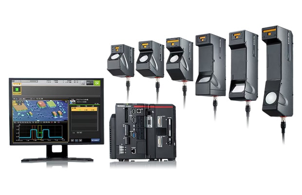
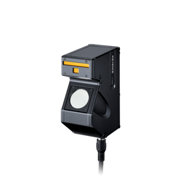
2D/3D Laser Profiler
Ultra-high-definition measurement of 3200 points/profile represents the cross-sectional shape in detail, quantifying indicators such as height, step, width, and angle. Height images generated from height data are not easily affected by color variation caused by wood grain, knots, or vessels, making it difficult to mistake color changes for defects. For knot inspection, gray-scale images acquired simultaneously with height images can be used. The 3D position correction function corrects for target misalignment and tilt, and the profile alignment function corrects for the effects of vibration during transport, allowing inspection points to track automatically. It is not easily affected by changes in distance or height differences, enabling clear imaging even for targets whose diameter changes significantly, such as logs. Inspections can be set up simply by choosing from a wide variety of measurement tools that measure steps, widths, cross-sectional areas, angles, and more, and it also supports inspection of long targets during transport. It also supports NG notification via judgment output and saving of measured values and images using the FTP server function.
Get Detailed Materials on the LJ-X8000 Series
You can download a free catalog summarizing sensor head specifications, measurement tools, and system configurations.
Examples of Use in Wood and Wood-Based Building Materials
It is used for everything from grading to shape measurement after processing and full-length thickness control.
Wood Grading and Knot Inspection
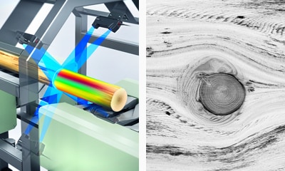
The size and shape of wood are measured and used for grading. Because judgment is based on shape, it is not easily affected by the wood grain, allowing for inspection of dents, and knots are inspected using gray-scale images acquired at the same time.
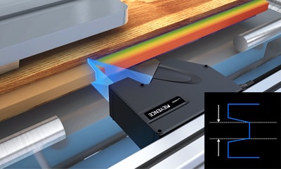
Measurement of Tongue and Groove Shape After Processing
A line laser is applied to the side of flooring material immediately after processing to measure the width and step from the cross-sectional shape of the tongue and groove. Because the 3D data averages out the roughness of the wood surface, stable measurement and inspection are possible even if there is roughness.
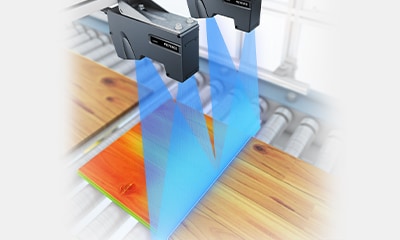
3D Inspection of Finished Material Surfaces
The surface of the board during transport is captured using height data to detect shape defects such as dents and cracks, which are then used for grading. It is not easily affected by the shading of the wood grain color, and knots can be inspected using gray-scale images acquired at the same time.
Frequently Asked Questions About Wood and Lumber Scanning
Q Will color variation in the wood grain be misidentified as a defect?
A
Because judgment is based on the physical quantity of height, shape defects can be evaluated without being easily affected by color changes due to wood grain or vessels. Defects that are distinguished by color, such as knots, are inspected using gray-scale images acquired at the same time.
Q Is measurement stable even on rough wood surfaces?
A
Yes, it is stable. Since height images are not easily affected by surface colors or patterns, the shape can be captured even on rough wood. We will propose settings and sensor heads according to the surface conditions.
Q Can targets with significantly different diameters, such as logs, be measured?
A
Yes, they can be measured. Because it is less susceptible to distance changes and height differences, clear images can be captured even for targets with varying diameters. We will propose the sensor head models, quantity, and layout based on the required measurement range and the area you want to capture.
Q Does the configuration change between the sawing process and the finishing process?
A
The purpose of the sawing process is to obtain log profiles (as a basis for lumber breakdown decisions), while the finishing process aims for full-length management of the finished shape and thickness. Since the targets to be measured and the required fields of view differ, we design the configuration for each process.
Q Can the thickness be measured over the entire length?
A
Yes, it can be measured. A configuration based on rollers supports inline full-length measurement, allowing you to understand thickness variations in the width direction as well. This is effective for managing glulam and CLT laminas.
Q Will the inspection points align even if the position shifts during conveyance?
A
Yes, they will align. The 3D position correction function corrects for target misalignment and tilt, and the profile alignment function corrects for the effects of vibration during conveyance, allowing the inspection points to follow automatically.