Manage Probe and Socket Wear With Numerical Values. Determine Replacement Timing by Dimensions, Not by Appearance.
If you wait until contact failures increase before replacing them, you will first incur losses in testing-process yield and re-measurement man-hours. We will introduce a method to quantify the wear, protrusion, and coplanarity of pin tips and determine the replacement cycle based on data.
Inquiries regarding dimensional management of probes and test sockets
Three Things That Happen If You Do Not Manage the Status of Jigs With Numerical Values
Contact failures can occur as a result of gradual changes in the jig.
Judging Good Parts as Defective
If the tips of probe pins wear out and the protrusion amount is insufficient, contact becomes unstable. Although they are rejected as defective in test results, the actual cause is the jig, not the device. If they pass after re-measurement, you can still notice it, but if they go undetected, good parts will be discarded. If you do not manage the status of the jig as dimensions, you cannot distinguish whether the variation in test results is due to the jig or the device.
Replacement Cycle Depends on Intuition and Experience
The judgment of "it’s about time to replace" depends on the operator’s experience. Replacing too early increases jig costs, while delaying it increases defects and re-measurement man-hours. By periodically recording the wear amount and coplanarity of pin tips as numerical values, you can see the level at which contact failures begin to increase. This allows you to determine the replacement timing as a control value rather than by intuition.
Variations in a Large Number of Pins Cannot Be Tracked by Observation
A large number of pins are lined up on probe cards and test sockets. While observing each pin one by one with a microscope is suitable for looking at the state of the tip shape in detail, it takes too much time to track the height variation of all pins every time. To use this in operation, a measurement method that can quantify a large number of pins at once based on the same standard is required.
4 Steps to Quantitatively Manage the Status of Jigs
Separate observation and quantification, and incorporate what can be quantified into periodic measurements.
- 1 Determine the dimensions to manage – STEP 1. Decide which of the following to use as the control value: pin tip height (protrusion amount), coplanarity between pins, or pin tip wear amount. If the control value is not decided, measurement cannot be used for judgment.
- 2 Measure height from the reference plane – STEP 2. Obtain the height of each pin based on a surface that is unlikely to change, such as the housing surface or the seating surface of the socket. If the reference changes every time, it becomes impossible to distinguish between changes due to wear and setup errors.
- 3 Quantify pins all at once – STEP 3. If you use a method that obtains cross-sectional shapes all at once with a line laser, or obtains height data over an area, you can quantify a large number of pins together under the same conditions. Since it takes less time than measuring one by one, it can be incorporated into periodic measurements.
- 4 Determine the replacement cycle by comparing with the number of uses – STEP 4. Record the measured values along with the number of touchdowns and operating hours. By comparing the trend of wear amount with the timing of contact failures, you can determine the level at which replacement is required as a control value.
Comparison of Methods for Understanding the Status of Probes and Sockets
This comparison considers height quantification, ease of integration into periodic measurements, and ease of observation.
| Perspective | Laser profile method (LJ-X8000 Series) |
White light interferometry method (WI-5000 Series) |
Observation with a microscope |
|---|---|---|---|
Pin tip height (protrusion amount) |
Laser profile method (LJ-X8000 Series)
◎ Calculated collectively from cross-sectional shapes
|
White light interferometry method (WI-5000 Series)
◎ Calculated from surface height data
|
Observation with a microscope
△ Reading from the focal position
|
Coplanarity of multiple pins |
Laser profile method (LJ-X8000 Series)
◎ Determined from height profiles
|
White light interferometry method (WI-5000 Series)
○ Batch measurement of the surface within the measurement range (large targets are measured in sections using an XY stage)
|
Observation with a microscope
× Impractical
|
Observation of tip shape and wear |
Laser profile method (LJ-X8000 Series)
○ Shape can be assessed
|
White light interferometry method (WI-5000 Series)
○ Shape can be assessed
|
Observation with a microscope
◎ Detailed observation under magnification
|
Can it be used for routine measurement? |
Laser profile method (LJ-X8000 Series)
◎ Acquire all pins while moving the target
|
White light interferometry method (WI-5000 Series)
○ Acquire in a short time for each field of view
|
Observation with a microscope
× Requires many man-hours
|
Operator-to-operator variation |
Laser profile method (LJ-X8000 Series)
◎ Unlikely to occur
|
White light interferometry method (WI-5000 Series)
◎ Unlikely to occur
|
Observation with a microscope
△ Depends on reading
|
Compatibility with metallic luster and plated surfaces |
Laser profile method (LJ-X8000 Series)
◎ Stable with stray light suppression function
|
White light interferometry method (WI-5000 Series)
◎ Coaxial measurement of specular reflection is also possible
|
Observation with a microscope
△ Dependent on lighting conditions
|
Recording of measured values |
Laser profile method (LJ-X8000 Series)
◎ Can be saved and output
|
White light interferometry method (WI-5000 Series)
◎ Can be saved and output
|
Observation with a microscope
△ Saved as an image
|
Separate Microscopic Observation From Dimensional Measurement for Management
A microscope is suitable for detailed observation of conditions such as how the tips are crushed or how far the plating has peeled off. On the other hand, for determining the replacement cycle, such as “how many µm the height has decreased” or “how many µm of variation there is between pins,” a method that can collectively quantify multiple pins based on the same standard is suitable. By separating observation and quantification and incorporating only what can be quantified into periodic measurements, operations will run smoothly.
Products That Support Pin Height and Coplanarity Measurement
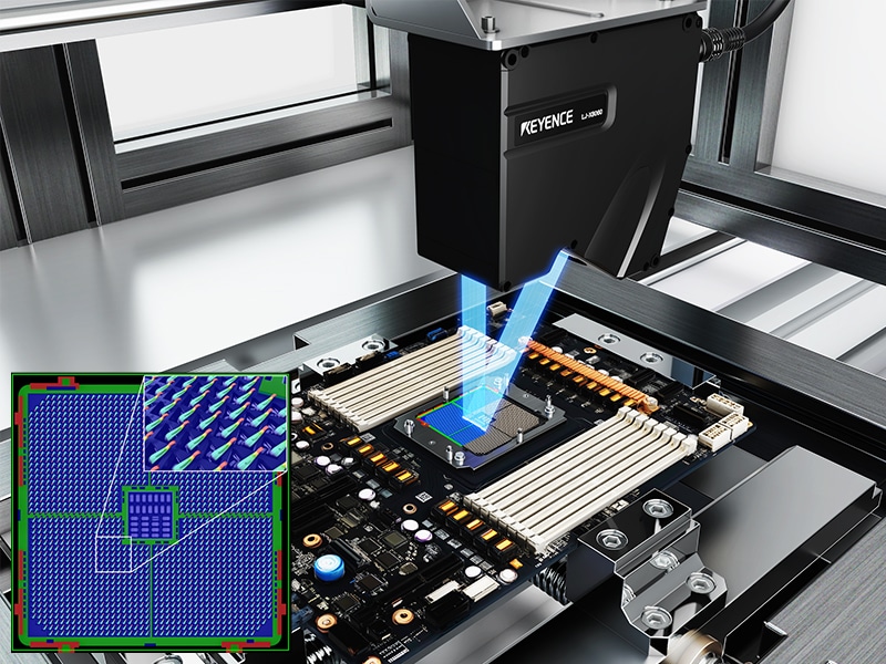
This is an inline profile measurement system that acquires cross-sections with a line laser and collectively quantifies the heights of multiple pins.
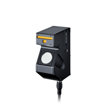
Supports Height and Coplanarity Measurement of Multiple Pins — LJ-X8000 Series
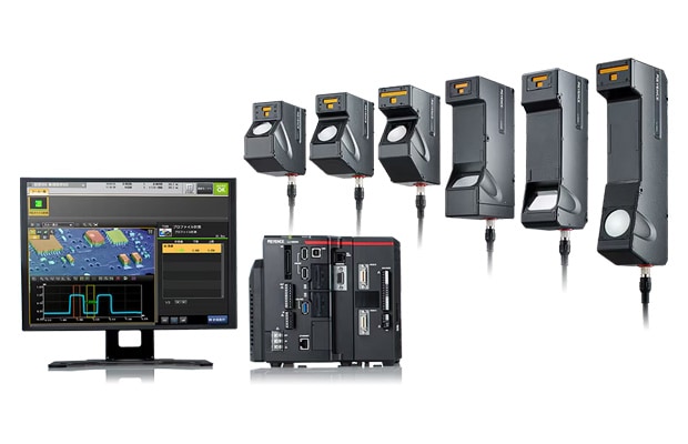
2D/3D Laser Profiler
This is an ultra high-definition inline profile measurement system that uses the laser profile method. With ultra-high-definition measurement of 3200 points/profile, even the tip shapes of thin pins can be represented as cross-sections, allowing the height (protrusion amount) and pitch of each pin to be quantified simultaneously. Because the target is moved while acquiring cross-sections with a line laser, even probe cards and test sockets with many pins can be evaluated collectively without measuring them one by one. For multiple reflections and diffuse reflections that are problematic with targets where metal is densely packed, the stray light suppression function works to obtain stable shapes even on plated surfaces. With the single-shot HDR function, even if highly reflective metal pins and low-reflective resin housings are in the same field of view, both can be captured in a single image. With the 3D position correction function, even if the placement of the jig changes slightly each time, the height can be evaluated from the reference plane, making it difficult for setup errors to affect the measured values. Measurement items can be set simply by choosing from a variety of measurement tools that measure steps, heights, angles, etc., and the FTP server function allows measured values and shape images to be saved and used for trend management.
Get Detailed Materials for the LJ-X8000 Series
You can download a free catalog summarizing the measurement range, specifications, and measurement tools.
Inquiries regarding dimensional management of probes and test sockets
Examples of Pin and Terminal Dimensional Measurement
Here are examples of quantifying the height and protrusion amount of pins and terminals.
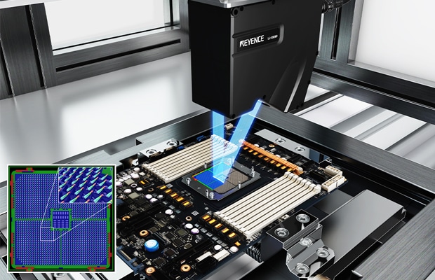
Contact Height Inspection of CPU Sockets
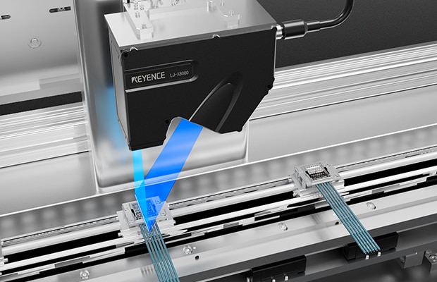
Contacts of CPU sockets mounted on server boards are measured collectively while scanning with a stage. The height of each pin tip is color-coded and displayed, allowing pins with crushing or sinking to be found numerically (LJ-X8000 Series).
Pin Height Inspection of High-Speed Connectors
For connectors with an increased number of pins for high-speed communication, the height of each pin is measured collectively during transfer. Short pins, which are difficult to distinguish by image alone, can be found by height values, helping to prevent defective products from escaping (LJ-X8000 Series).
Electrostatic Chuck Pin Height Measurement
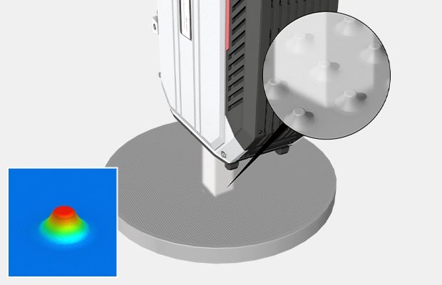
Combined with a rotary and XY stage, the height of each pin is automatically measured one by one. Because measurement results can be output linked to the measurement locations, the heights of a large number of pins can be automatically quantified (WI-5000 Series).
Precision Connector Coplanarity Measurement
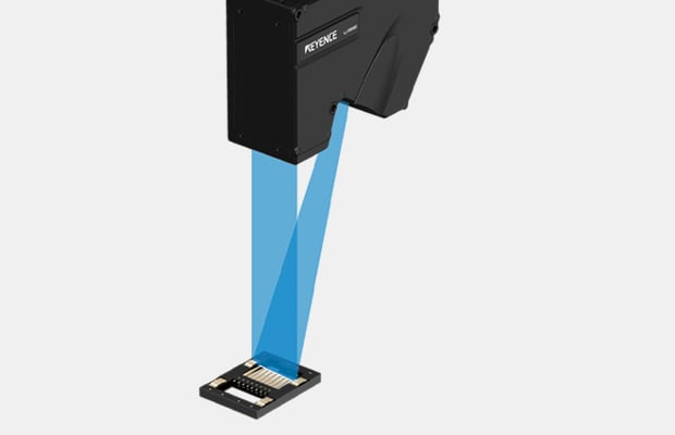
A line laser is projected onto the terminal rows of precision connectors, which are becoming smaller and lower profile, to acquire the height of each terminal at once. The variation in height between terminals can be numerically evaluated as coplanarity (LJ-X8000 Series).
Frequently Asked Questions About Probe and Test Socket Inspection
Q How is pin wear quantified?
A
Using surfaces that are unlikely to change, such as the housing surface or seating surface, as a reference, the tip height of each pin is acquired, and the difference from the initial state is managed as the amount of wear. By fixing the reference surface, it is possible to distinguish between setup errors and changes due to wear.
Q How does this differ from observation with a microscope?
A
Microscopes are suitable for detailed observation of how the tips are crushed. On the other hand, dimensional measurement methods are better suited for quickly quantifying “how many micrometers the height has decreased” and “how much variation there is between pins” for a large number of pins, which are used to determine the replacement cycle.
Q Does the measurement time increase even if there are many pins?
A
With methods that continuously acquire cross-sections using a line laser or acquire height data collectively over an area, the measurement time does not increase as much as measuring each pin one by one, even if the number of pins increases. This can be integrated into operations as a periodic measurement.
Q Can pins with metallic luster be measured stably?
A
Multiple reflections can be a problem with targets where metal is densely packed, but the effects can be suppressed using the stray light suppression function. Even when highly reflective metal pins and low-reflective plastic housings coexist, they can be captured in a single image using the single-shot HDR function.
Q Does the measurement need to be performed with the jig removed?
A
The jig is removed from the tester and set in the measurement position, but there is no need to disassemble it because the shape is acquired non-contact from above. It is common practice to set the jig in the measurement position during periodic maintenance.
Q How should the replacement cycle be determined?
A
Record the measured values along with the number of touchdowns and operating hours, and compare them with the occurrence of contact failures. Once the level of wear or coplanarity at which failures begin to increase is identified, set it as the control value that serves as the replacement criterion.