KV-X Series × SP-N Series
EtherNet/IP™ Connection Guide
KV-Return to KV Series Connection Guide
KV-X Series × SP-N Series EtherNet/IP™ Connection Guide
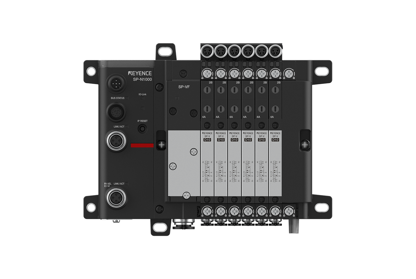
SP-N Series

Contents
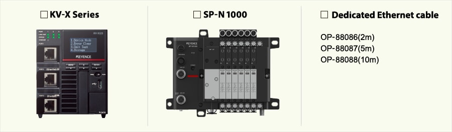
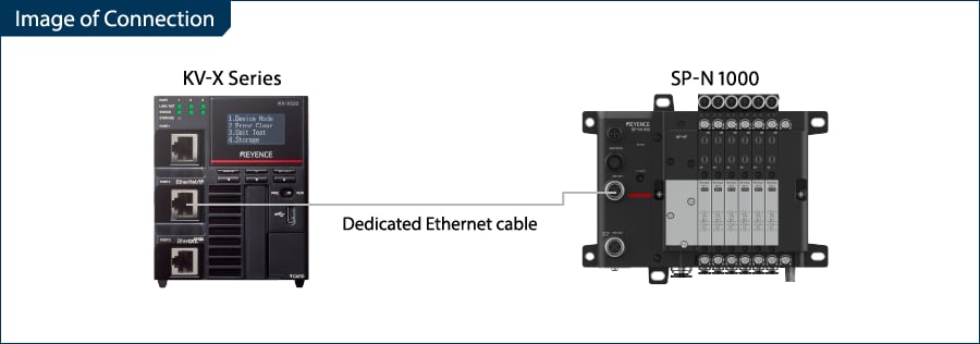
Step 1 : Devices Required for Connection
Please prepare the following devices.
Step 2 : SP-N Series[EtherNet/IP]Settings
Use the SP Setting Tool to configure the network settings of the SP-N Series.
This guide uses the following IP addresses assigned to the KV-X Series and SP-N Series as an example.
| KV-X Series | SP-N Series |
|---|---|
| 192.168.0.10 | 192.168.0.1 |
Setting Method Using SP Setting Tool
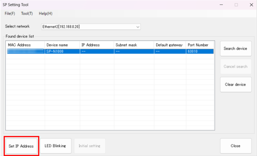
1. After connecting the PC and SP-N Series with an Ethernet cable, start SP Setting Tool and search for communication units in the network using Search device.
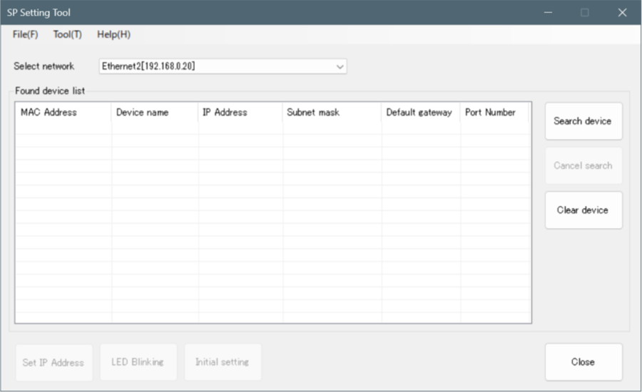
2. Select the target communication unit and click Set IP Address.
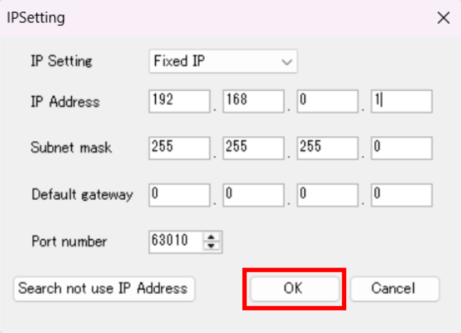
3. Enter the IP address and subnet mask, then click [OK].
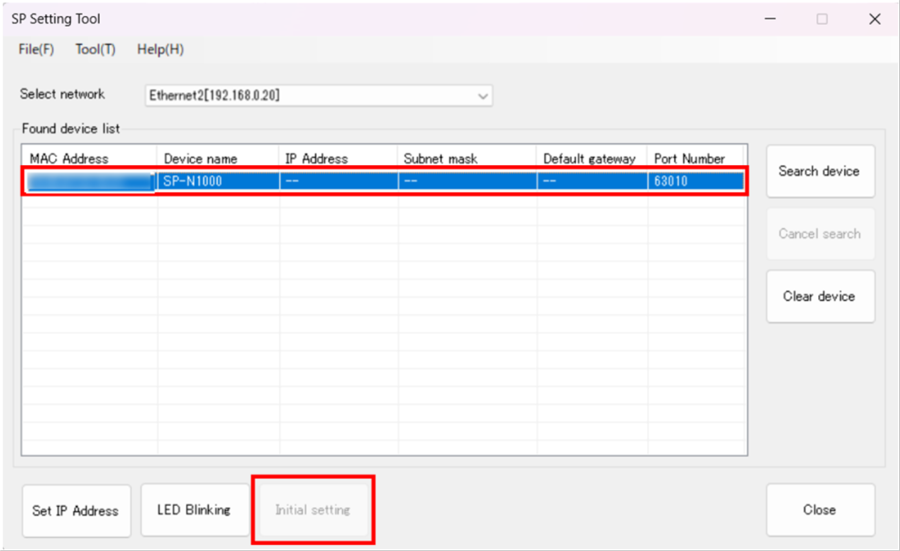
4. Configure the communication protocol. Select the target communication unit and click Initial setting.
5. After selecting "EtherNet/IP, Modbus/TCP, MC Protocol, SLMP", click [OK].
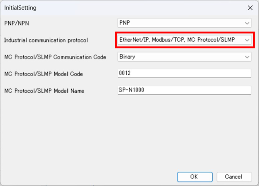
This completes the settings on the SP-N Series side.
Step 3 : KV-X Series Connection Settings
This section explains how to connect with a fictitious device called "Vendor Series". Replace the "Vender Series" with the device to be connected.
One point
For the KV Series with a CPU function version of 2.0 or later, variables can be assigned to the connection of EtherNet/IP.
When assigning variables to the connection of EtherNet/IP®, check the box of “Displays the variable setting dialog when updating the EtherNet/IP settings (E)” for “Other settings” of “System settings” on the “CPU system settings” dialog.
The “CPU system settings” dialog is displayed by selecting [Display (V)] ⇒ [CPU system settings (P)] from the ”KV STUDIO” menu.
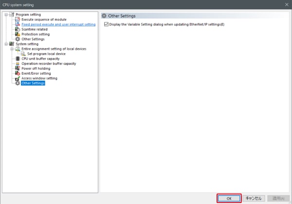
When the box of "Displays the variable setting dialog when updating the EtherNet/IP settings (E)" is checked, at the timing when the EtherNet/IP setting is updated and the changed content of the unit editor is confirmed, a dialog to assign variables to the connection is displayed.
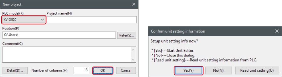
1. Start up the KV STUDIO and create a new project. Set the model option to “KV-X520” and click [OK].
A [Confirm unit configuration setting] dialog box is displayed. Click [Yes (Y)].
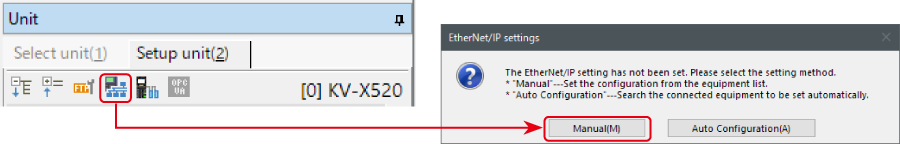
2. The unit editor is displayed. On the “Setup unit(2)” tab, click the icon of EtherNet/IP setting. A configuration type selection dialog box is displayed. Click [Manual (M)].
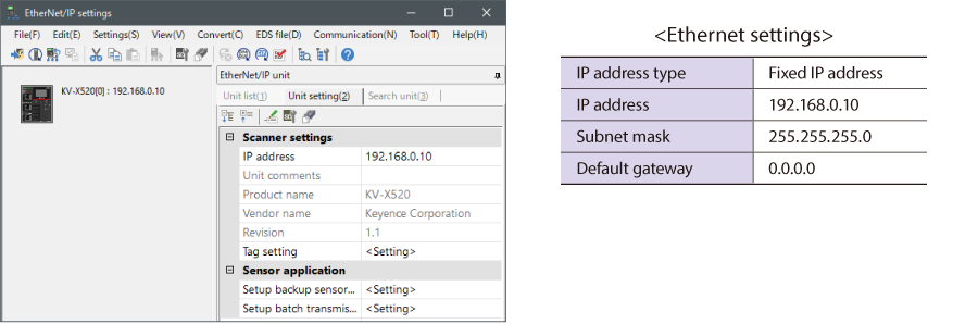
3. On the “Unit setting (2)” tab, set the IP address for KV-X Series. In this example, configure the setting as shown below.
* Step 4 needs to be performed to import a sensor setting file. When the sensor setting file has already been imported, proceed to Step 5.
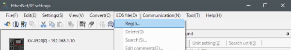
4. Select [EDS file (D)] → [Reg (I)] to import the KEYENCE sensor setting file(ez1 file) or EDS file.
* Download the sensor setting file from the KEYENCE website.
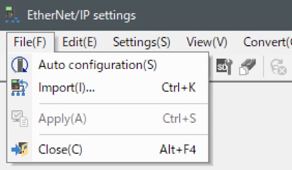
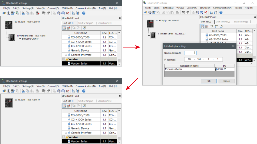
5. With the KV-X Series and the EtherNet/IP devices connected using the Ethernet cable, select [File (F)] → [Auto configuration (S)] on the [EtherNet/IP settings] window.
6. When the configuration on the unit editor differs from that of the actual device, a dialog for confirming transfer of the project is displayed. With the PC and KV-X Series connected using the USB cable, click [Yes (Y)].
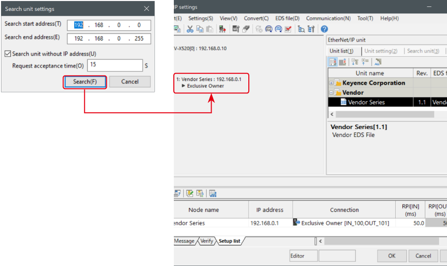
7. When transfer of the project is completed, the [Search unit settings] dialog is displayed. Then click [Search (F)]. After the auto configuration is completed, "Vendor Series" is automatically registered. Then click [OK] to close the [EtherNet/IP settings] window.
8. Click [OK] on the unit editor to exit.
One point
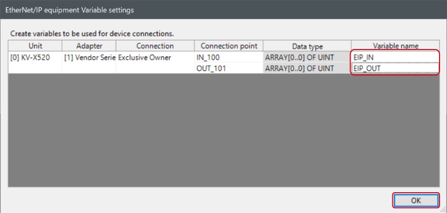
When the box of "Displays the variable setting dialog when updating the EtherNet/IP settings (E)" is checked, the [EtherNet/IP equipment Variable settings] dialog is displayed.
Enter the name of variable assigned to the connection, and click [OK].
- The way of Device Configuration Settings manually
In the [Unit list (1)] tab of “EtherNet/IP Settings”, drag and drop "Vendor Series" and create a device configuration.
Transferring and Monitoring Setting Data
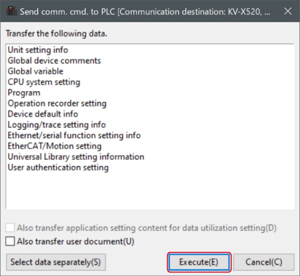
1. From the menu, select [Monitor/Simulator (N)] > [Transfer to PLC (W) → Monitor mode (C)].
In the [Send comm. cmd. to PLC] dialog box, click [Execute(E)].
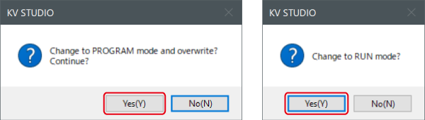
2. If the following dialog box is displayed before and after transferring the data, click [Yes] both times.
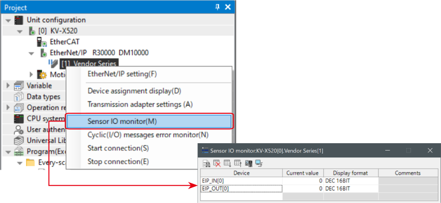
3. Right-click on “Vender Series” in the workspace, and select [Sensor IO monitor (M)].
Scores and other information can be easily monitored.
One point
The information can also be checked on a graph by starting up the real time chart monitor.
Right-click on “Sensor I/O monitor” and select [Real time chart monitor (H)].
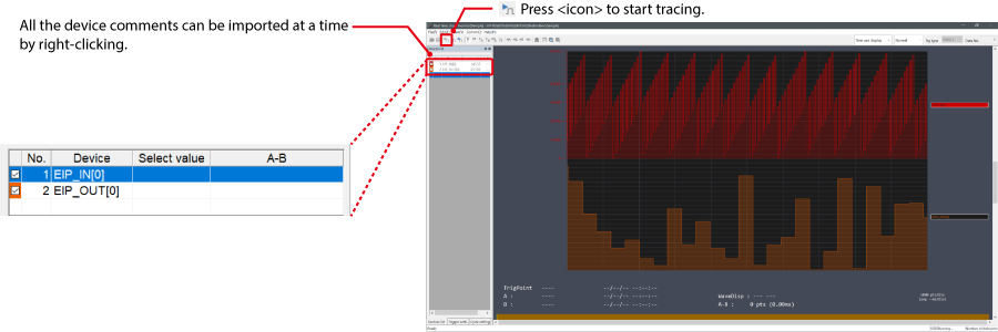
Range adjustment is not required since the real time chart monitor performs scaling automatically.
When Manipulating Parameters with a Program
Changing the Setting Values
The setting values of the sensors can be changed by the following two methods:
A : Change from a PC
B : Change from a ladder program
A : Change from a PC
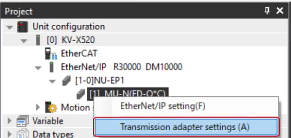
To change the settings from a PC, use the transmission adapter function in KV STUDIO.
1. Expand the unit configuration in the workspace. Right-click on "Vender Series" and select [Transmission adapter settings (A)].
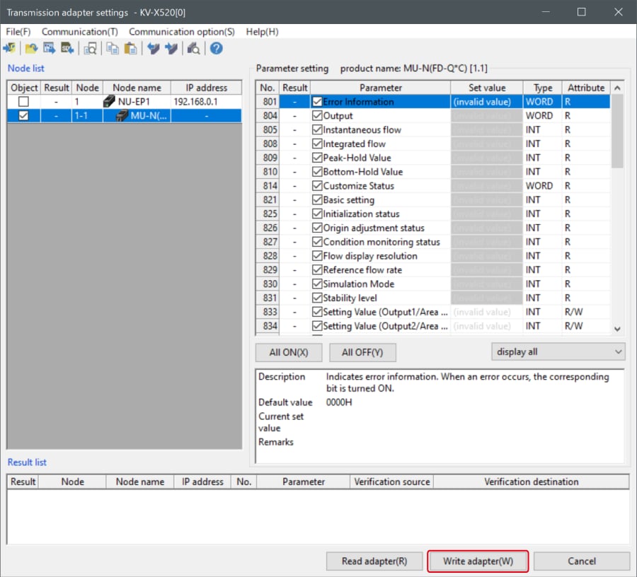
2. Place a check mark in Setting Value for "Vender Series" and enter the setting value.
Click [Write adapter (W)] to write the setting value to the sensor.
*To read the setting value of a sensor, select [Read adapter (R)].
B : Changed from a ladder program
Use message communication to change the setting values from a ladder program.
To perform message communication with KV STUDIO, use the sensor setting commands (SPWR [sensor parameter write] and SPRD [sensor parameter read]).
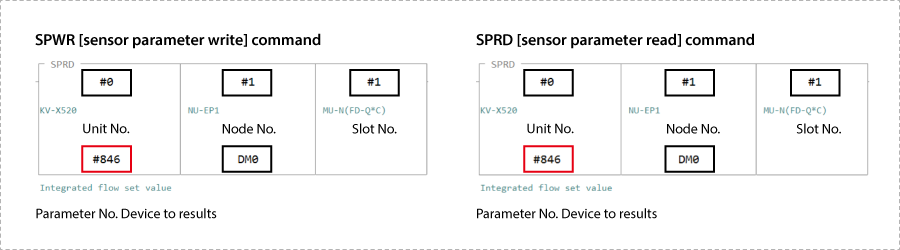
1. In Editor mode, create a ladder program as shown below.
* For the parameter numbers, refer to Parameter list.
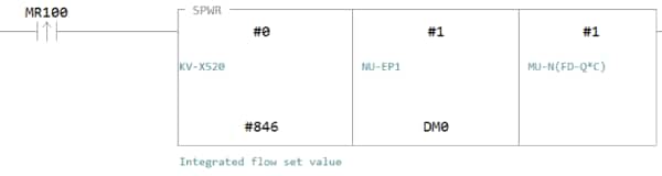
2. Transfer the ladder program.
3. When MR100 is turned on, the setting value is changed.
* Store the setting value in DM4 ([Leading device to store results] + 4).
One point
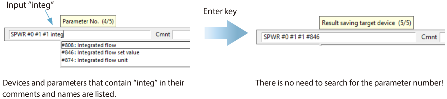
RT (Real-Time) Edit function
When you use a ladder program, you can input device comments or parameter names directly to have input candidates be searched for and displayed automatically.
Reference : Variable Assignment
Here, the variable names are VariableName_IN and VariableName_OUT, but replace them with the variable names entered in step 8 of Step 3.
Available Connections
The connections available for the SP-N Series are as follows:
| Connection name | Connection point | Input/Output | Size (words) | Application type |
|---|---|---|---|---|
| Basic Monitor Data/Control Data | IN_100 | Input | 28 | Exclusive owner |
| OUT_110 | Output | 12 | ||
| Basic Monitor Data | IN_100 | Input | 28 | Input Only |
| ー | ー | ー | ||
| Advanced Monitor Data/Control Data | IN_101 | Input | 252 | Exclusive owner |
| OUT_110 | Output | 12 | ||
| Advanced Monitor Data | IN_101 | Input | 252 | Input Only |
| ― | ― | ― | ||
| Advanced Monitor Data (Sensor)/Control Data | IN_102 | Input | 204 | Exclusive owner |
| OUT_110 | Output | 12 | ||
| Advanced Monitor Data (Sensor) | IN_102 | Input | 204 | Input Only |
| ― | ― | ― | ||
| Advanced Monitor Data ID1-8/Control Data | IN_103 | Input | 92 | Exclusive owner |
| OUT_110 | Output | 12 | ||
| Advanced Monitor Data ID1-8 | IN_103 | Input | 92 | Input Only |
| ― | ― | ― | ||
| Advanced Monitor Data ID1-16/Control Data | IN_104 | Input | 172 | Exclusive owner |
| OUT_110 | Output | 12 | ||
| Advanced Monitor Data ID1-16 | IN_104 | Input | 172 | Input Only |
| ― | ― | ― |
Input(SP-N→KV-X, Connection Point: IN_100)
| Variable Name | Data Type | Item | |
|---|---|---|---|
| Member Name | |||
| VariableName_IN | SP_N1000_IN100 | ||
| Ready | BOOL | Ready | |
| Run | BOOL | Running | |
| MonitorConnected | BOOL | Monitor Connected | |
| StartupMode | BOOL | Startup Mode | |
| OperationError | BOOL | Error Operation Disabled | |
| NormalError | BOOL | Normal Error | |
| Warning | BOOL | Warning | |
| ConnectedStatus | SP_N1000_ConnectedStatus | ||
| SensorOutput | ARRAY[0..23] OF SP_N1000_SensorOutput | ||
Input(SP-N→KV-X, Connection Point: IN_101)
| Structure Name | Data Type | Item | |
|---|---|---|---|
| Member Name | |||
| VariableName_IN | SP_N1000_IN101 | ||
| Ready | BOOL | Ready | |
| Run | BOOL | Running | |
| MonitorConnected | BOOL | Monitor Connected | |
| StartupMode | BOOL | Startup Mode | |
| OperationError | BOOL | Error Operation Disabled | |
| NormalError | BOOL | Error General | |
| ErrorUnitID | UINT | Error Unit ID | |
| ErrorCode | UINT | Error Code | |
| WarningUnitID | UINT | Warning Unit ID | |
| WarningCode | UINT | Warning Code | |
| ConnectedStatus | SP_N1000_ConnectedStatus | ||
| ID41_Pressure | UINT | ID41 Pressure Value | |
| ID42_Pressure | UINT | ID42 Pressure Value | |
| ID43_Pressure | UINT | ID43 Pressure Value | |
| ID44_Pressure | UINT | ID44 Pressure Value | |
| Sensor_Info | ARRAY[0..23] OF SP_N1000_SensorInfo | ||
Input(SP-N→KV-X, Connection Point: IN_102)
| Structure Name | Data Type | Item | |
|---|---|---|---|
| Member Name | |||
| VariableName_IN | SP_N1000_IN102 | ||
| Ready | BOOL | Ready | |
| Run | BOOL | Running | |
| MonitorConnected | BOOL | Monitor Connected | |
| StartupMode | BOOL | Startup Mode | |
| OperationError | BOOL | Error Operation Disabled | |
| NormalError | BOOL | Error General | |
| ErrorUnitID | UINT | Error Unit ID | |
| ErrorCode | UINT | Error Code | |
| WarningUnitID | UINT | Warning Unit ID | |
| WarningCode | UINT | Warning Code | |
| ConnectedStatus | SP_N1000_ConnectedStatus | ||
| ID41_Pressure | UINT | ID41 Pressure Value | |
| ID42_Pressure | UINT | ID42 Pressure Value | |
| ID43_Pressure | UINT | ID43 Pressure Value | |
| ID44_Pressure | UINT | ID44 Pressure Value | |
| Sensor_Data | ARRAY[0..23] OF SP_N1000_SensorData | ||
Input(SP-N→KV-X, Connection Point: IN_103)
| Structure Name | Data Type | Item | |
|---|---|---|---|
| Member Name | |||
| VariableName_IN | SP_N1000_IN103 | ||
| Ready | BOOL | Ready | |
| Run | BOOL | Running | |
| MonitorConnected | BOOL | Monitor Connected | |
| StartupMode | BOOL | Startup Mode | |
| OperationError | BOOL | Error Operation Disabled | |
| NormalError | BOOL | Error General | |
| ErrorUnitID | UINT | Error Unit ID | |
| ErrorCode | UINT | Error Code | |
| WarningUnitID | UINT | Warning Unit ID | |
| WarningCode | UINT | Warning Code | |
| ConnectedStatus | SP_N1000_ID1_8_ConnectedStatus | ||
| ID41_Pressure | UINT | ID41 Pressure Value | |
| ID42_Pressure | UINT | ID42 Pressure Value | |
| ID43_Pressure | UINT | ID43 Pressure Value | |
| ID44_Pressure | UINT | ID44 Pressure Value | |
| Sensor_Info | ARRAY[0..7] OF SP_N1000_SensorInfo | ||
Input(SP-N→KV-X, Connection Point: IN_104)
| Structure Name | Data Type | Item | |
|---|---|---|---|
| Member Name | |||
| VariableName_IN | SP_N1000_IN104 | ||
| Ready | BOOL | Ready | |
| Run | BOOL | Running | |
| MonitorConnected | BOOL | Monitor Connected | |
| StartupMode | BOOL | Startup Mode | |
| OperationError | BOOL | Error Operation Disabled | |
| NormalError | BOOL | Error General | |
| ErrorUnitID | UINT | Error Unit ID | |
| ErrorCode | UINT | Error Code | |
| WarningUnitID | UINT | Warning Unit ID | |
| WarningCode | UINT | Warning Code | |
| ConnectedStatus | SP_N1000_ID1_16_ConnectedStatus | ||
| ID41_Pressure | UINT | ID41 Pressure Value | |
| ID42_Pressure | UINT | ID42 Pressure Value | |
| ID43_Pressure | UINT | ID43 Pressure Value | |
| ID44_Pressure | UINT | ID44 Pressure Value | |
| Sensor_Info | ARRAY[0..15] OF SP_N1000_SensorInfo | ||
Structure (Input)
| Structure Name | Data Type | Item | |
|---|---|---|---|
| Member Name | |||
| SP_N1000_ConnectedStatus | |||
| ID1_CH1 | BOOL | ID1 CH1 CS-Link/Connected Device Status | |
| ID1_CH2 | BOOL | ID1 CH2 CS-Link/Connected Device Status | |
| ID2_CH1 | BOOL | ID2 CH1 CS-Link/Connected Device Status | |
| ID2_CH2 | BOOL | ID2 CH2 CS-Link/Connected Device Status | |
| ID3_CH1 | BOOL | ID3 CH1 CS-Link/Connected Device Status | |
| ID3_CH2 | BOOL | ID3 CH2 CS-Link/Connected Device Status | |
| ID4_CH1 | BOOL | ID4 CH1 CS-Link/Connected Device Status | |
| ID4_CH2 | BOOL | ID4 CH2 CS-Link/Connected Device Status | |
| ID5_CH1 | BOOL | ID5 CH1 CS-Link/Connected Device Status | |
| ID5_CH2 | BOOL | ID5 CH2 CS-Link/Connected Device Status | |
| ID6_CH1 | BOOL | ID6 CH1 CS-Link/Connected Device Status | |
| ID6_CH2 | BOOL | ID6 CH2 CS-Link/Connected Device Status | |
| ID7_CH1 | BOOL | ID7 CH1 CS-Link/Connected Device Status | |
| ID7_CH2 | BOOL | ID7 CH2 CS-Link/Connected Device Status | |
| ID8_CH1 | BOOL | ID8 CH1 CS-Link/Connected Device Status | |
| ID8_CH2 | BOOL | ID8 CH2 CS-Link/Connected Device Status | |
| ID9_CH1 | BOOL | ID9 CH1 CS-Link/Connected Device Status | |
| ID9_CH2 | BOOL | ID9 CH2 CS-Link/Connected Device Status | |
| ID10_CH1 | BOOL | ID10 CH1 CS-Link/Connected Device Status | |
| ID10_CH2 | BOOL | ID10 CH2 CS-Link/Connected Device Status | |
| ID11_CH1 | BOOL | ID11 CH1 CS-Link/Connected Device Status | |
| ID11_CH2 | BOOL | ID11 CH2 CS-Link/Connected Device Status | |
| ID12_CH1 | BOOL | ID12 CH1 CS-Link/Connected Device Status | |
| ID12_CH2 | BOOL | ID12 CH2 CS-Link/Connected Device Status | |
| ID13_CH1 | BOOL | ID13 CH1 CS-Link/Connected Device Status | |
| ID13_CH2 | BOOL | ID13 CH2 CS-Link/Connected Device Status | |
| ID14_CH1 | BOOL | ID14 CH1 CS-Link/Connected Device Status | |
| ID14_CH2 | BOOL | ID14 CH2 CS-Link/Connected Device Status | |
| ID15_CH1 | BOOL | ID15 CH1 CS-Link/Connected Device Status | |
| ID15_CH2 | BOOL | ID15 CH2 CS-Link/Connected Device Status | |
| ID16_CH1 | BOOL | ID16 CH1 CS-Link/Connected Device Status | |
| ID16_CH2 | BOOL | ID16 CH2 CS-Link/Connected Device Status | |
| ID17_CH1 | BOOL | ID17 CH1 CS-Link/Connected Device Status | |
| ID17_CH2 | BOOL | ID17 CH2 CS-Link/Connected Device Status | |
| ID18_CH1 | BOOL | ID18 CH1 CS-Link/Connected Device Status | |
| ID18_CH2 | BOOL | ID18 CH2 CS-Link/Connected Device Status | |
| ID19_CH1 | BOOL | ID19 CH1 CS-Link/Connected Device Status | |
| ID19_CH2 | BOOL | ID19 CH2 CS-Link/Connected Device Status | |
| ID20_CH1 | BOOL | ID20 CH1 CS-Link/Connected Device Status | |
| ID20_CH2 | BOOL | ID20 CH2 CS-Link/Connected Device Status | |
| ID21_CH1 | BOOL | ID21 CH1 CS-Link/Connected Device Status | |
| ID21_CH2 | BOOL | ID21 CH2 CS-Link/Connected Device Status | |
| ID22_CH1 | BOOL | ID22 CH1 CS-Link/Connected Device Status | |
| ID22_CH2 | BOOL | ID22 CH2 CS-Link/Connected Device Status | |
| ID23_CH1 | BOOL | ID23 CH1 CS-Link/Connected Device Status | |
| ID23_CH2 | BOOL | ID23 CH2 CS-Link/Connected Device Status | |
| ID24_CH1 | BOOL | ID24 CH1 CS-Link/Connected Device Status | |
| ID24_CH2 | BOOL | ID24 CH2 CS-Link/Connected Device Status | |
Structure (Input)
| Structure Name | Data Type | Item | |
|---|---|---|---|
| Member Name | |||
| SP_N1000_SensorOutput | |||
| CH1_Sensor_OUT1 | BOOL | CH1 Sensor OUT1 | |
| CH1_Sensor_OUT2 | BOOL | CH1 Sensor OUT2 | |
| CH1_Sensor_OUT3 | BOOL | CH1 Sensor OUT3 | |
| CH1_Sensor_OUT4 | BOOL | CH1 Sensor OUT4 | |
| CH2_Sensor_OUT1 | BOOL | CH2 Sensor OUT1 | |
| CH2_Sensor_OUT2 | BOOL | CH2 Sensor OUT2 | |
| CH2_Sensor_OUT3 | BOOL | CH2 Sensor OUT3 | |
| CH2_Sensor_OUT4 | BOOL | CH2 Sensor OUT4 | |
Structure (Input)
| Structure Name | Data Type | Item | |
|---|---|---|---|
| Member Name | |||
| SP_N1000_ID1_8_ConnectedStatus | |||
| ID1_CH1 | BOOL | ID1 CH1 CS-Link/Connected Device Status | |
| ID1_CH2 | BOOL | ID1 CH2 CS-Link/Connected Device Status | |
| ID2_CH1 | BOOL | ID2 CH1 CS-Link/Connected Device Status | |
| ID2_CH2 | BOOL | ID2 CH2 CS-Link/Connected Device Status | |
| ID3_CH1 | BOOL | ID3 CH1 CS-Link/Connected Device Status | |
| ID3_CH2 | BOOL | ID3 CH2 CS-Link/Connected Device Status | |
| ID4_CH1 | BOOL | ID4 CH1 CS-Link/Connected Device Status | |
| ID4_CH2 | BOOL | ID4 CH2 CS-Link/Connected Device Status | |
| ID5_CH1 | BOOL | ID5 CH1 CS-Link/Connected Device Status | |
| ID5_CH2 | BOOL | ID5 CH2 CS-Link/Connected Device Status | |
| ID6_CH1 | BOOL | ID6 CH1 CS-Link/Connected Device Status | |
| ID6_CH2 | BOOL | ID6 CH2 CS-Link/Connected Device Status | |
| ID7_CH1 | BOOL | ID7 CH1 CS-Link/Connected Device Status | |
| ID7_CH2 | BOOL | ID7 CH2 CS-Link/Connected Device Status | |
| ID8_CH1 | BOOL | ID8 CH1 CS-Link/Connected Device Status | |
| ID8_CH2 | BOOL | ID8 CH2 CS-Link/Connected Device Status | |
Structure (Input)
| Structure Name | Data Type | Item | |
|---|---|---|---|
| Member Name | |||
| SP_N1000_ID1_16_ConnectedStatus | |||
| ID1_CH1 | BOOL | ID1 CH1 CS-Link/Connected Device Status | |
| ID1_CH2 | BOOL | ID1 CH2 CS-Link/Connected Device Status | |
| ID2_CH1 | BOOL | ID2 CH1 CS-Link/Connected Device Status | |
| ID2_CH2 | BOOL | ID2 CH2 CS-Link/Connected Device Status | |
| ID3_CH1 | BOOL | ID3 CH1 CS-Link/Connected Device Status | |
| ID3_CH2 | BOOL | ID3 CH2 CS-Link/Connected Device Status | |
| ID4_CH1 | BOOL | ID4 CH1 CS-Link/Connected Device Status | |
| ID4_CH2 | BOOL | ID4 CH2 CS-Link/Connected Device Status | |
| ID5_CH1 | BOOL | ID5 CH1 CS-Link/Connected Device Status | |
| ID5_CH2 | BOOL | ID5 CH2 CS-Link/Connected Device Status | |
| ID6_CH1 | BOOL | ID6 CH1 CS-Link/Connected Device Status | |
| ID6_CH2 | BOOL | ID6 CH2 CS-Link/Connected Device Status | |
| ID7_CH1 | BOOL | ID7 CH1 CS-Link/Connected Device Status | |
| ID7_CH2 | BOOL | ID7 CH2 CS-Link/Connected Device Status | |
| ID8_CH1 | BOOL | ID8 CH1 CS-Link/Connected Device Status | |
| ID8_CH2 | BOOL | ID8 CH2 CS-Link/Connected Device Status | |
| ID9_CH1 | BOOL | ID9 CH1 CS-Link/Connected Device Status | |
| ID9_CH2 | BOOL | ID9 CH2 CS-Link/Connected Device Status | |
| ID10_CH1 | BOOL | ID10 CH1 CS-Link/Connected Device Status | |
| ID10_CH2 | BOOL | ID10 CH2 CS-Link/Connected Device Status | |
| ID11_CH1 | BOOL | ID11 CH1 CS-Link/Connected Device Status | |
| ID11_CH2 | BOOL | ID11 CH2 CS-Link/Connected Device Status | |
| ID12_CH1 | BOOL | ID12 CH1 CS-Link/Connected Device Status | |
| ID12_CH2 | BOOL | ID12 CH2 CS-Link/Connected Device Status | |
| ID13_CH1 | BOOL | ID13 CH1 CS-Link/Connected Device Status | |
| ID13_CH2 | BOOL | ID13 CH2 CS-Link/Connected Device Status | |
| ID14_CH1 | BOOL | ID14 CH1 CS-Link/Connected Device Status | |
| ID14_CH2 | BOOL | ID14 CH2 CS-Link/Connected Device Status | |
| ID15_CH1 | BOOL | ID15 CH1 CS-Link/Connected Device Status | |
| ID15_CH2 | BOOL | ID15 CH2 CS-Link/Connected Device Status | |
| ID16_CH1 | BOOL | ID16 CH1 CS-Link/Connected Device Status | |
| ID16_CH2 | BOOL | ID16 CH2 CS-Link/Connected Device Status | |
Structure (Input)
| Structure Name | Data Type | Item | |
|---|---|---|---|
| Member Name | |||
| SP_N1000_SensorInfo | |||
| CH1_Sensor_OUT1 | BOOL | CH1 Sensor OUT1 | |
| CH1_Sensor_OUT2 | BOOL | CH1 Sensor OUT2 | |
| CH1_Sensor_OUT3 | BOOL | CH1 Sensor OUT3 | |
| CH1_Sensor_OUT4 | BOOL | CH1 Sensor OUT4 | |
| CH1_Sensor_SystemError | BOOL | CH1 Sensor System Error | |
| CH1_Sensor_OverCurrent | BOOL | CH1 Sensor Over Current Error | |
| CH1_Sensor_EEPROMError | BOOL | CH1 Sensor EEPROM Error | |
| CH1_Sensor_OUT1Misalign | BOOL | CH1 Sensor OUT1 Misalignment | |
| CH1_Sensor_OUT2Misalign | BOOL | CH1 Sensor OUT2 Misalignment | |
| CH1_Sensor_OUT1Imp_Lv_Exceeded | BOOL | CH1 Sensor OUT1 Impact Level Exceeded | |
| CH1_Sensor_OUT2Imp_Lv_Exceeded | BOOL | CH1 Sensor OUT2 Impact Level Exceeded | |
| CH1_Sensor_OutOfDetection | BOOL | CH1 Sensor Out of Detection Range | |
| CH1_Sensor_ImpactLevel | UINT | CH1 Sensor Impact Level | |
| CH1_Sensor_Speed | INT | CH1 Sensor Speed | |
| CH1_Sensor_Position | INT | CH1 Sensor Position | |
| CH1_SPC_OUT1 | BOOL | CH1 SP-C OUT1 | |
| CH1_SPC_OUT2 | BOOL | CH1 SP-C OUT2 | |
| CH1_SPC_OverCurrent | BOOL | CH1 SP-C Over Current Error | |
| CH1_SPC_EEPROMError | BOOL | CH1 SP-C EEPROM Error | |
| CH1_SPC_SensorDisconnected | BOOL | CH1 SP-C Sensor Disconnected | |
| CH1_SPC_Incomp_OutSetting | BOOL | CH1 SP-C Incomplete Output Setting | |
| CH1_SPC_StrokeTimeWarning | BOOL | CH1 SP-C Stroke Time Warning | |
| CH1_SPC_SlowerSpeedAreaExceeded | BOOL | CH1 SP-C Slower Speed Area Exceeded | |
| CH2_Sensor_OUT1 | BOOL | CH2 Sensor OUT1 | |
| CH2_Sensor_OUT2 | BOOL | CH2 Sensor OUT2 | |
| CH2_Sensor_OUT3 | BOOL | CH2 Sensor OUT3 | |
| CH2_Sensor_OUT4 | BOOL | CH2 Sensor OUT4 | |
| CH2_Sensor_SystemError | BOOL | CH2 Sensor System Error | |
| CH2_Sensor_OverCurrent | BOOL | CH2 Sensor Over Current Error | |
| CH2_Sensor_EEPROMError | BOOL | CH2 Sensor EEPROM Error | |
| CH2_Sensor_OUT1Misalign | BOOL | CH2 Sensor OUT1 Misalign | |
| CH2_Sensor_OUT2Misalign | BOOL | CH2 Sensor OUT2 Misalign | |
| CH2_Sensor_OUT1Imp_Lv_Exceeded | BOOL | CH2 Sensor OUT1 Impact Level Exceeded | |
| CH2_Sensor_OUT2Imp_Lv_Exceeded | BOOL | CH2 Sensor OUT2 Impact Level Exceeded | |
| CH2_Sensor_OutOfDetection | BOOL | CH2 Sensor Out of Detection Range | |
| CH2_Sensor_ImpactLevel | UINT | CH2 Sensor Impact Level | |
| CH2_Sensor_Speed | INT | CH2 Sensor Speed | |
| CH2_Sensor_Position | INT | CH2 Sensor Position | |
| CH2_SPC_OUT1 | BOOL | CH2 SP-C OUT1 | |
| CH2_SPC_OUT2 | BOOL | CH2 SP-C OUT2 | |
| CH2_SPC_OverCurrent | BOOL | CH2 SP-C Over Current Error | |
| CH2_SPC_EEPROMError | BOOL | CH2 SP-C EEPROM Error | |
| CH2_SPC_SensorDisconnected | BOOL | CH2 SP-C Sensor Disconnected | |
| CH2_SPC_Incomp_OutSetting | BOOL | CH2 SP-C Incomplete Output Setting | |
| CH2_SPC_StrokeTimeWarning | BOOL | CH2 SP-C Stroke Time Warning | |
| CH2_SPC_SlowerSpeedAreaExceeded | BOOL | CH2 SP-C Slower Speed Area Exceeded | |
Structure (Input)
| Structure Name | Data Type | Item | |
|---|---|---|---|
| Member Name | |||
| SP_N1000_SensorData | |||
| CH1_Sensor_OUT1 | BOOL | CH1 Sensor OUT1 | |
| CH1_Sensor_OUT2 | BOOL | CH1 Sensor OUT2 | |
| CH1_Sensor_OUT3 | BOOL | CH1 Sensor OUT3 | |
| CH1_Sensor_OUT4 | BOOL | CH1 Sensor OUT4 | |
| CH1_Sensor_SystemError | BOOL | CH1 Sensor System Error | |
| CH1_Sensor_OverCurrent | BOOL | CH1 Sensor Over Current Error | |
| CH1_Sensor_EEPROMError | BOOL | CH1 Sensor EEPROM Error | |
| CH1_Sensor_OUT1Misalign | BOOL | CH1 Sensor OUT1 Misalignment | |
| CH1_Sensor_OUT2Misalign | BOOL | CH1 Sensor OUT2 Misalignment | |
| CH1_Sensor_OUT1Imp_Lv_Exceeded | BOOL | CH1 Sensor OUT1 Impact Level Exceeded | |
| CH1_Sensor_OUT2Imp_Lv_Exceeded | BOOL | CH1 Sensor OUT2 Impact Level Exceeded | |
| CH1_Sensor_OutOfDetection | BOOL | CH1 Sensor Out of Detection Range | |
| CH1_Sensor_ImpactLevel | UINT | CH1 Sensor Impact Level | |
| CH1_Sensor_Speed | INT | CH1 Sensor Speed | |
| CH1_Sensor_Position | INT | CH1 Sensor Position | |
| CH2_Sensor_OUT1 | BOOL | CH2 Sensor OUT1 | |
| CH2_Sensor_OUT2 | BOOL | CH2 Sensor OUT2 | |
| CH2_Sensor_OUT3 | BOOL | CH2 Sensor OUT3 | |
| CH2_Sensor_OUT4 | BOOL | CH2 Sensor OUT4 | |
| CH2_Sensor_SystemError | BOOL | CH2 Sensor System Error | |
| CH2_Sensor_OverCurrent | BOOL | CH2 Sensor Over Current Error | |
| CH2_Sensor_EEPROMError | BOOL | CH2 Sensor EEPROM Error | |
| CH2_Sensor_OUT1Misalign | BOOL | CH2 Sensor OUT1 Misalign | |
| CH2_Sensor_OUT2Misalign | BOOL | CH2 Sensor OUT2 Misalign | |
| CH2_Sensor_OUT1Imp_Lv_Exceeded | BOOL | CH2 Sensor OUT1 Impact Level Exceeded | |
| CH2_Sensor_OUT2Imp_Lv_Exceeded | BOOL | CH2 Sensor OUT2 Impact Level Exceeded | |
| CH2_Sensor_OutOfDetection | BOOL | CH2 Sensor Out of Detection Range | |
| CH2_Sensor_ImpactLevel | UINT | CH2 Sensor Impact Level | |
| CH2_Sensor_Speed | INT | CH2 Sensor Speed | |
| CH2_Sensor_Position | INT | CH2 Sensor Position | |
Output (KV-X→SP-N)
| Variable Name | Data Type | Item | |
|---|---|---|---|
| Member Name | |||
| VariableName_OUT | SP_N1000_OUT110 | ||
| ValveOutControl | SP_N1000_ValveOutControl | ||
| ExtMfdControl | ARRAY[0..3] OF SP_N1000_ExtMfdControl | ||
Structure (Output)
| Structure Name | Data Type | Item | |
|---|---|---|---|
| Member Name | |||
| SP_N1000_ValveOutControl | |||
| ID1_Valve4A_CH1 | BOOL | ID1 Valve4A Control/CH1 Control Output | |
| ID1_Valve2B_CH2 | BOOL | ID1 Valve2B Control/CH2 Control Output | |
| ID2_Valve4A_CH1 | BOOL | ID2 Valve4A Control/CH1 Control Output | |
| ID2_Valve2B_CH2 | BOOL | ID2 Valve2B Control/CH2 Control Output | |
| ID3_Valve4A_CH1 | BOOL | ID3 Valve4A Control/CH1 Control Output | |
| ID3_Valve2B_CH2 | BOOL | ID3 Valve2B Control/CH2 Control Output | |
| ID4_Valve4A_CH1 | BOOL | ID4 Valve4A Control/CH1 Control Output | |
| ID4_Valve2B_CH2 | BOOL | ID4 Valve2B Control/CH2 Control Output | |
| ID5_Valve4A_CH1 | BOOL | ID5 Valve4A Control/CH1 Control Output | |
| ID5_Valve2B_CH2 | BOOL | ID5 Valve2B Control/CH2 Control Output | |
| ID6_Valve4A_CH1 | BOOL | ID6 Valve4A Control/CH1 Control Output | |
| ID6_Valve2B_CH2 | BOOL | ID6 Valve2B Control/CH2 Control Output | |
| ID7_Valve4A_CH1 | BOOL | ID7 Valve4A Control/CH1 Control Output | |
| ID7_Valve2B_CH2 | BOOL | ID7 Valve2B Control/CH2 Control Output | |
| ID8_Valve4A_CH1 | BOOL | ID8 Valve4A Control/CH1 Control Output | |
| ID8_Valve2B_CH2 | BOOL | ID8 Valve2B Control/CH2 Control Output | |
| ID9_Valve4A_CH1 | BOOL | ID9 Valve4A Control/CH1 Control Output | |
| ID9_Valve2B_CH2 | BOOL | ID9 Valve2B Control/CH2 Control Output | |
| ID10_Valve4A_CH1 | BOOL | ID10 Valve4A Control/CH1 Control Output | |
| ID10_Valve2B_CH2 | BOOL | ID10 Valve2B Control/CH2 Control Output | |
| ID11_Valve4A_CH1 | BOOL | ID11 Valve4A Control/CH1 Control Output | |
| ID11_Valve2B_CH2 | BOOL | ID11 Valve2B Control/CH2 Control Output | |
| ID12_Valve4A_CH1 | BOOL | ID12 Valve4A Control/CH1 Control Output | |
| ID12_Valve2B_CH2 | BOOL | ID12 Valve2B Control/CH2 Control Output | |
| ID13_Valve4A_CH1 | BOOL | ID13 Valve4A Control/CH1 Control Output | |
| ID13_Valve2B_CH2 | BOOL | ID13 Valve2B Control/CH2 Control Output | |
| ID14_Valve4A_CH1 | BOOL | ID14 Valve4A Control/CH1 Control Output | |
| ID14_Valve2B_CH2 | BOOL | ID14 Valve2B Control/CH2 Control Output | |
| ID15_Valve4A_CH1 | BOOL | ID15 Valve4A Control/CH1 Control Output | |
| ID15_Valve2B_CH2 | BOOL | ID15 Valve2B Control/CH2 Control Output | |
| ID16_Valve4A_CH1 | BOOL | ID16 Valve4A Control/CH1 Control Output | |
| ID16_Valve2B_CH2 | BOOL | ID16 Valve2B Control/CH2 Control Output | |
| ID17_Valve4A_CH1 | BOOL | ID17 Valve4A Control/CH1 Control Output | |
| ID17_Valve2B_CH2 | BOOL | ID17 Valve2B Control/CH2 Control Output | |
| ID18_Valve4A_CH1 | BOOL | ID18 Valve4A Control/CH1 Control Output | |
| ID18_Valve2B_CH2 | BOOL | ID18 Valve2B Control/CH2 Control Output | |
| ID19_Valve4A_CH1 | BOOL | ID19 Valve4A Control/CH1 Control Output | |
| ID19_Valve2B_CH2 | BOOL | ID19 Valve2B Control/CH2 Control Output | |
| ID20_Valve4A_CH1 | BOOL | ID20 Valve4A Control/CH1 Control Output | |
| ID20_Valve2B_CH2 | BOOL | ID20 Valve2B Control/CH2 Control Output | |
| ID21_Valve4A_CH1 | BOOL | ID21 Valve4A Control/CH1 Control Output | |
| ID21_Valve2B_CH2 | BOOL | ID21 Valve2B Control/CH2 Control Output | |
| ID22_Valve4A_CH1 | BOOL | ID22 Valve4A Control/CH1 Control Output | |
| ID22_Valve2B_CH2 | BOOL | ID22 Valve2B Control/CH2 Control Output | |
| ID23_Valve4A_CH1 | BOOL | ID23 Valve4A Control/CH1 Control Output | |
| ID23_Valve2B_CH2 | BOOL | ID23 Valve2B Control/CH2 Control Output | |
| ID24_Valve4A_CH1 | BOOL | ID24 Valve4A Control/CH1 Control Output | |
| ID24_Valve2B_CH2 | BOOL | ID24 Valve2B Control/CH2 Control Output | |
Structure (Output)
| Structure Name | Data Type | Item | |
|---|---|---|---|
| Member Name | |||
| SP_N1000_ExtMfdControl | |||
| Pin1_Output | BOOL | Pin1 Output | |
| Pin2_Output | BOOL | Pin2 Output | |
| Pin3_Output | BOOL | Pin3 Output | |
| Pin4_Output | BOOL | Pin4 Output | |
| Pin5_Output | BOOL | Pin5 Output | |
| Pin6_Output | BOOL | Pin6 Output | |
| Pin7_Output | BOOL | Pin7 Output | |
| Pin8_Output | BOOL | Pin8 Output | |
| Pin9_Output | BOOL | Pin9 Output | |
| Pin10_Output | BOOL | Pin10 Output | |
| Pin11_Output | BOOL | Pin11 Output | |
| Pin12_Output | BOOL | Pin12 Output | |
| Pin13_Output | BOOL | Pin13 Output | |
| Pin14_Output | BOOL | Pin14 Output | |
| Pin15_Output | BOOL | Pin15 Output | |
| Pin16_Output | BOOL | Pin16 Output | |
| Pin17_Output | BOOL | Pin17 Output | |
| Pin18_Output | BOOL | Pin18 Output | |
| Pin19_Output | BOOL | Pin19 Output | |
| Pin20_Output | BOOL | Pin20 Output | |
| Pin21_Output | BOOL | Pin21 Output | |
| Pin22_Output | BOOL | Pin22 Output | |
| Pin23_Output | BOOL | Pin23 Output | |
| Pin24_Output | BOOL | Pin24 Output | |
| Pin25_Output | BOOL | Pin25 Output | |
