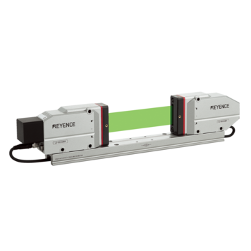
Capture Web Edges Without Stopping: Quantify Edge Positions Even for Fluttering Webs
Meandering causes wrinkles, winding misalignment, and edge trimming defects. With the LS-9000 Series, whether it is transparent film or metal foil, the edge position of a web fluttering up and down can be captured at high speed, and the meandering amount can be quantified and fed back to the EPC.
Inquiries about web edge position and meandering measurement
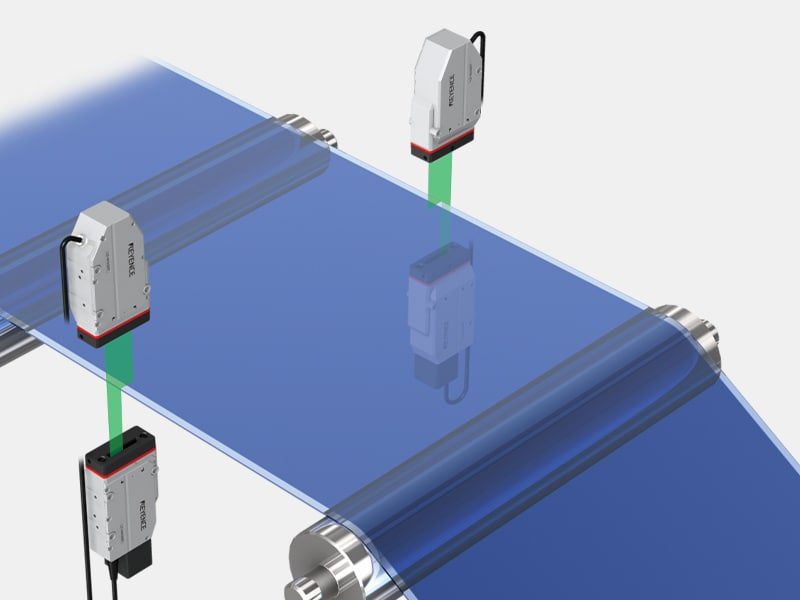
Three Reasons Why Web Edge Positions Should Be Measured
Meandering is the source of all kinds of conveyance issues.
Meandering Causes Wrinkles and Winding Misalignment Downstream
When a web wanders in the width direction, tension becomes uneven between rolls, causing wrinkles and folds. During winding, the edges do not align, resulting in a misaligned product roll. Although both issues are discovered in the final process, the cause lies in the upstream conveyance. By continuously monitoring the edge position and quantifying the amount of misalignment, you can identify at which roll the disturbance occurred.
The Position of Edge Trimming Determines the Product Width
In converting, the edges are trimmed to achieve the product width. If trimming is performed while the web is meandering, the trim allowance will vary from place to place, causing the product width to fall out of specification. A larger trim allowance reduces the yield rate, while a smaller one leaves untrimmed areas. Measuring the edge position and reflecting it in the trimmer position achieves both width accuracy and high yield rate.
Values Fluctuate Due to Materials and Fluttering
Transparent films have weak reflection and light blocking, making detection unstable with methods that capture edges based on the difference between light and dark. Conversely, metal foils have strong reflection, which can cause saturation under certain conditions. Furthermore, because a running web flutters up and down due to tension fluctuations, methods where values change when the distance to the target changes cannot distinguish between widthwise meandering and vertical fluttering. For any material, a method is required where the edge position value does not change with variations in distance.
4 Steps From Edge Position to Meandering Control
Rather than simply measuring, this process covers feedback to the EPC or trimmer as a complete sequence.
- 1 Continuous detection of edge position – Implementation 1. The edge position is calculated from the position where the edge of the web crosses a beam of uniform parallel light. With sampling at 16,000 Hz, the movement of the edge can be tracked even on high-speed lines.
- 2 Quantification of meandering amount – Implementation 2. The difference from the reference position is quantified as the meandering amount. Short-cycle wandering in the width direction and long-cycle drift caused by rolls can be evaluated separately.
- 3 Feedback to EPC – Implementation 3. The meandering amount is output as an analog signal and fed back to the EPC (edge position control) to control the guide rolls. The position can be corrected without stopping conveyance.
- 4 Width management and recording – Implementation 4. The width can be calculated from the edge positions of two sensor heads. Even if the width changes depending on the product type, it can be handled by changing the head positions, and the measured values can be saved and used to record the total length.
Comparison of Web Edge Detection Methods
The suitability of each method varies under conditions such as transparency, high reflectivity, and fluttering.
| Detection items / Conditions | LS-9000 Series (Optical/Thrubeam method) |
Ultrasonic edge sensor | Thrubeam type laser detection sensor (Single element) |
Area camera (Image processing) |
|---|---|---|---|---|
(1) Continuous detection of edge position |
LS-9000 Series (Optical/Thrubeam method)
◎ Continuous output of positions as numerical values
|
Ultrasonic edge sensor
○ Position can be detected
|
Thrubeam type laser detection sensor (single element)
△ Accuracy close to presence/absence detection
|
Area camera (image processing)
○ Position can be detected
|
(2) Quantification of meandering amount |
LS-9000 Series (optical/thrubeam type)
◎ Quantifies the difference from the reference
|
Ultrasonic edge sensor
○ Can be quantified
|
Thrubeam type laser detection sensor (single element)
× Difficult to quantify
|
Area camera (image processing)
○ Can be quantified
|
(3) Compatibility with transparent films |
LS-9000 Series (optical/thrubeam type)
◎ Detects at the light-blocking position
|
Ultrasonic edge sensor
◎ Works with any material
|
Thrubeam type laser detection sensor (single element)
△ Light may pass through, making detection impossible
|
Area camera (image processing)
△ Difficult to obtain contrast
|
(4) Compatibility with metal foil and highly reflective materials |
LS-9000 Series (optical/thrubeam type)
◎ Resistant to saturation
|
Ultrasonic edge sensor
◎ Unaffected
|
Thrubeam type laser detection sensor (single element)
△ Unstable due to reflection
|
Area camera (image processing)
△ Glare occurs
|
(5) Resistance to fluttering (distance variation) |
LS-9000 Series (optical/thrubeam)
◎ Stable position even if distance changes
|
Ultrasonic edge sensor
△ Sensitivity changes with distance
|
Thrubeam type laser detection sensor (single element)
△ Affected
|
Area camera (image processing)
△ Depends on focus conditions
|
Tracking high-speed lines |
LS-9000 Series (optical/thrubeam)
◎ 16,000 Hz
|
Ultrasonic edge sensor
△ Slow response
|
Thrubeam type laser detection sensor (single element)
○ High speed
|
Area camera (image processing)
△ Depends on imaging speed
|
Simultaneous width management |
LS-9000 Series (optical/thrubeam)
◎ Calculates width with 2 heads
|
Ultrasonic edge sensor
△ 2 units required
|
Thrubeam type laser detection sensor (single element)
× Practically impossible
|
Area camera (image processing)
○ Possible if within the field of view
|
Analog output to EPC |
LS-9000 Series (Optical/Thrubeam type)
◎ Direct analog output of the amount of meandering
|
Ultrasonic edge sensor
○ Supported
|
Thrubeam type laser detection sensor (single element)
× Cannot output position information
|
Area camera (image processing)
△ Conversion required
|
Why Choose the LS-9000 Series for Web Edge Detection
Because the LS-9000 Series determines the edge from the position where parallel light is blocked, it can capture the edge position of both transparent films and metal foils using the same configuration. Even if the web flutters up and down, the position value remains stable, and sampling at 16,000 Hz captures the movement of high-speed lines. In addition to outputting the amount of meandering as an analog signal to feed back to the EPC, a dual-head configuration allows width management to be handled with the same equipment.
Products for Web Edge Position and Meandering Measurement
This measurement system captures the edge position of a traveling web at high speed and quantifies the amount of meandering even if there is fluttering.
Supports Roll-to-Roll Edge Position and Meandering Management — LS-9000 Series
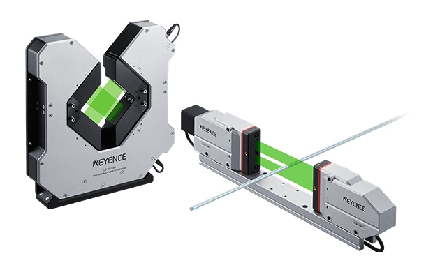
High-speed optical micrometer
This measurement system uses KEYENCE’s proprietary 3-CMOS x Green-LED method. It emits high-intensity Green-LED light as uniform parallel light and calculates the edge position from the light-to-dark transition of the light received by the CMOS. Because it detects the actual position where light is blocked, it can capture the edge of both transparent films and metal foils using the same configuration. The specially designed high-speed exposure CMOS achieves a fastest-in-class sampling rate of 16,000 Hz, capturing even short-cycle movements of a web traveling at high speed.
Even if the distance to the sensor changes, the light-blocking position does not change, so the value in the width direction remains stable even if the web flutters up and down due to tension fluctuations. Because the width can be determined from the edge positions of two sensor heads, changes in width for different product types can be handled simply by changing the head positions. The drive-less structure, which has no scanning drive parts like polygon mirrors, is less susceptible to degradation over time and is suitable for converting lines that operate continuously for long periods. The large-capacity data storage function stores measurement data, which can be transferred to Excel using the standard included setup support software LS-Navigator2.
Get Detailed Materials for the LS-9000 Series
You can download a free catalog summarizing the measurement range, specifications, and system configuration.
Inquiries about web edge position and meandering measurement
Application Examples in Roll-to-Roll Processes
It is used for everything from film meandering measurement to width management and edge curl detection.
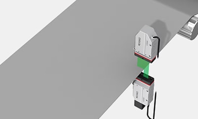
Film Meandering Measurement
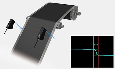
Meandering during conveyance, which causes wrinkles and processing defects, is monitored in a non-contact manner with ultra-high-speed measurement of 16,000 Hz. Because the amount of deviation is captured as a numerical value, it can be fed back to the control system.
Film Width Measurement
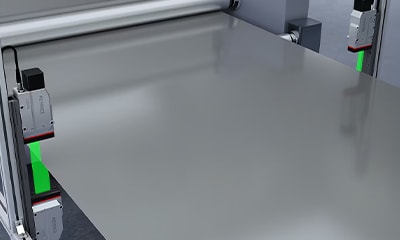
The width is calculated from the edge positions of two sensor heads. Even if the width changes depending on the product type, it can be handled by changing the head positions, allowing both width and meandering to be managed with the same equipment.
Film/Sheet Edge Curl Detection
Edge curl caused by thickness variation, tension, or blade wear is detected and represented in detail with ultra-high-definition measurement. This leads to quality control of edge trimming (LJ-X8000 Series).
Frequently Asked Questions About Web Edge Position and Meandering Measurement
Q Can edges be detected even on transparent films?
A
Yes, they can. Because the edge is determined from the exact position where the parallel light is blocked, it is virtually unaffected by the transparency or color of the target. Highly reflective materials such as metal foil can also be handled with the same configuration.
Q Will the values remain stable even if the web flutters up and down?
A
Yes, they will. Since the light-blocking position does not change even if the distance to the sensor changes, this method makes the position value in the width direction less susceptible to the effects of fluttering.
Q Can the meandering amount be fed back to the EPC?
A
Yes, it can. The difference from the reference position is calculated as the meandering amount, which can be fed back to the EPC (Edge Position Control) via analog output. The position can be corrected using guide rolls without stopping conveyance.
Q Can width management also be performed with the same equipment?
A
Yes, it can. Two sensor heads are placed at both ends, and the width is calculated from each end position. Even if the width changes depending on the product type, it can be handled simply by changing the head positions.
Q Can edge shape defects, such as edge curl, also be detected?
A
Since it is necessary to view the cross-sectional shape of the edge, a profiler (LJ-X8000 Series) is combined in that case. It is practical to divide the roles: using an optical micrometer for position and a profiler for shape.
Q Can it keep up even on high-speed lines?
A
Yes, it can. With the fastest sampling in its class, short-cycle fluctuations and long-cycle drift caused by rolls can be captured separately.