Image Dimension Measurement System
IM-X1000 series

Advantages Image Dimension Measurement System IM-X1000 series
Solves the Problems With Conventional Measurement Systems
Conventional Systems
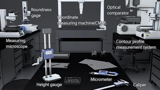
Slow, inconsistent and difficult
Conventional measurement systems often come with limitations. You’re typically restricted in where you can measure and what you can measure, which means multiple systems are needed for different tasks. They can also be slow, complicated to use, and prone to human error—often requiring highly experienced operators to get accurate results.
IM-X Series
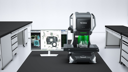
Fast, easy and accurate
The IM-X Series enables an all-in-one measuring solution that can handle a wide range of measurement capabilities, so there’s no need for multiple systems. And because measurements can be taken with just the push of a button, the process is much faster and easier. Even first-time users can get accurate results without the risk of errors.
Fast An Advanced Version of “Place and Press” That Dramatically Reduces Your Dimensional Measurement Workload
Fully Measure Parts in as Little as 1 Second Without Fixturing. Up to 5000 Dimensions per Part.
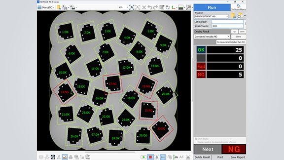
Simply place the part anywhere on the stage and press the measure button to perform instant, automatic measurement of the specified dimensions. The OK/NG result status is clearly displayed on the screen, making the inspection process easy for anyone to complete.
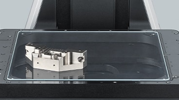
On the left side
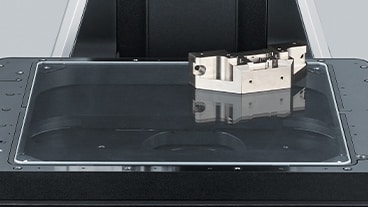
On the right side
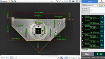
Instant measurement of specified dimensions
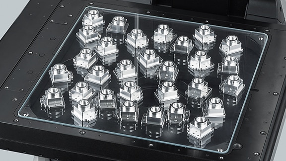
Measure up to 1000 Parts at the Same Time
Multiple parts can be placed on the stage and measured in one go. Even with a large number of parts, there’s no required fixturing, resulting in a significant reduction in work.
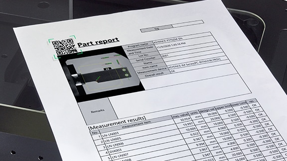
Quickly Access Programs Using QR Codes
QR codes for programs can be printed on inspection reports. This function ensures that even with an increased number of measurement file types, human errors such as incorrect program selection by the operator can be eliminated.
Easy Import Drawings and Automatically Create Programs
From Drawing to Program in Three Steps
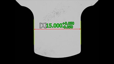
Automatically retrieves the information needed for measurement from the drawing. The operator simply clicks the points to be measured on the screen. The measurement program automatically reflects information such as elements required for the measurement points, design values, tolerances, etc. There is no longer any need to spend time reading and interpreting drawings to create a program.
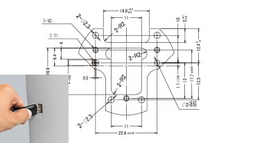
1. Import the drawing
Prepare and import drawing data for the part.
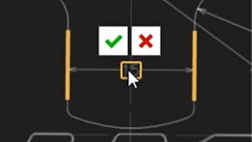
2. Click
On the drawing, click “Design value” for the dimension you want to measure.
3. Automatic creation
The program is created with the design values and the lower and upper tolerance limits set.
Scan and Import Physical Drawings
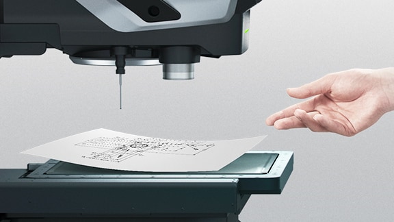
Drawings can be imported not only as DXF files, but also in image file formats such as PDF and JPEG. In addition, even paper drawings can be scanned and imported using the camera, meaning you can easily and efficiently create programs even when there is no electronic data on hand.
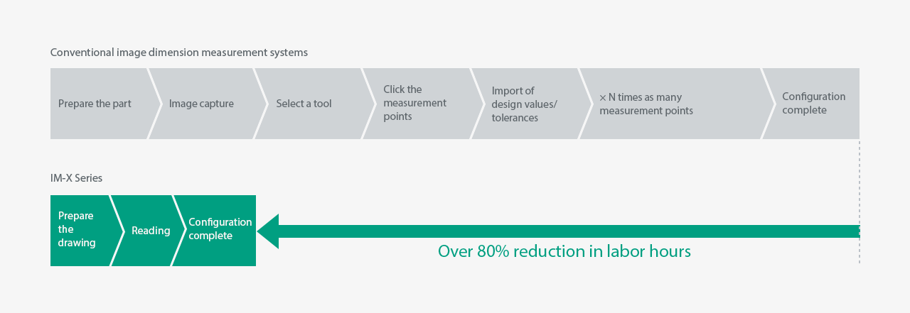
Greatly Reduce Program Creation Labor Hours by up to 80% With Batch Generation
When importing information from DXF data, all measurement points and design values/tolerances can be programmed in one go at the touch of a button. Dramatically reduces the amount of time required to create programs. This also leads to a significant increase in efficiency when measuring one-of-a-kind products.
Easy Fully Automated and Optimized Focus and Lighting
Automatically Determine Optimal Focus and Lighting With Smart Assist
Tasks such as focusing, illumination selection, and edge detection are now all automated. The measurement system itself can experiment with various conditions to find the optimal conditions for stability during continuous measurements. This allows anyone to reproduce measurements at an expert level.
Focus / Lighting / Edge Detection
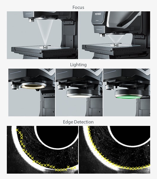
Determination of optimal conditions
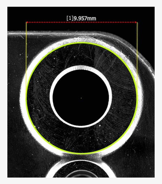
Intuitive Operation on Depth Composition Images
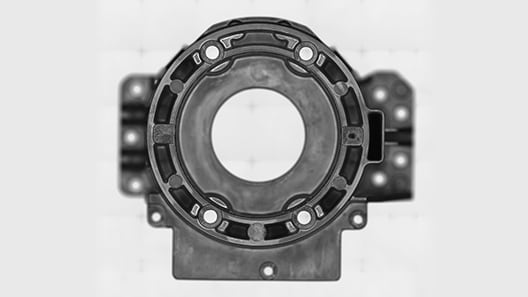
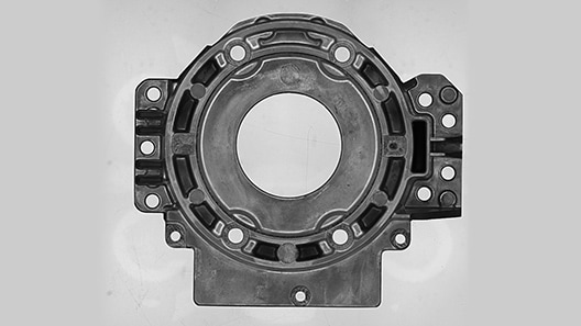
For parts with large height differences, conventional models display blurry images with single-point focus. With the IM-X Series, a depth composition image can be created first with the focus on all surfaces of the part, and then settings can be created based on that image. Quickly find the edges you want when indicating measurement points.
Conventional image
Depth composition image
Accurate Accurate Measurements With High Magnification and Clear Images Over a Wide Area
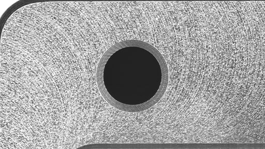
Equipped With a 20-Megapixel CMOS Sensor: Crisp, Clear Images for Precise Edge Detection
Equipped with an ultra-high-definition 20-megapixel CMOS sensor to visualize minute edges in coaxial illumination images that were difficult to see until now. This enables stable and accurate measurement of even the finest and most complex measurement points.
Before
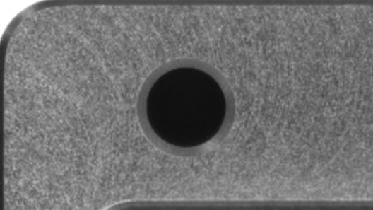
After
The Right Measurement Head for the Right Application
The stage and head can be separated, and there are two different head types to choose from with different magnifications and viewing angles. They can be easily swapped out on-site without the need for any special equipment, allowing you to use the head that is most suitable for your measurement needs.
Wide-Field IM head
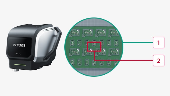
The large Ø100 mm diameter lens allows for simultaneous measurement of a wide area. The quick and efficient measurement is ideal for situations where inspection efficiency is a priority.
-
1IM head field of view
-
2Conventional microscope field of view
High-Accuracy LM head
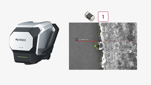
With an optical zoom of up to 50×, even the smallest details can be expanded and accurately measured. Very high 0.1 µm repeatability within the field of view, suitable for situations where inspection precision is a priority.
-
1Zoomed image of the capacitor electrode section