Smart Valve Manifold
SP-N/V series
Specs Smart Valve Manifold SP-N/V series
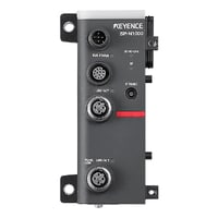
Communication Unit
|
Model |
SP-N1000 |
|||
|
Image |
|
|||
|
Type |
Communication unit |
|||
|
Max. number of connected units |
Valve unit |
24 *1 *2 *3 |
||
|
Distributed I/O unit |
Up to 3 *1 |
|||
|
Supply/exhaust unit |
8 *1 *2 |
|||
|
External manifold connection unit |
4 *1 *4 |
|||
|
I/O unit |
Up to 6 *1 |
|||
|
Communication interface |
Industrial communication port |
Supported networks |
EtherNet/IP™, PROFINET, Modbus/TCP, MC Protocol/SLMP, IO-Link (Class B , Specification v1.1/COM3) *5 |
|
|
Industrial communication port, Panel connection port (common) |
Connector type |
M12 (D-code) 4-pin, female |
||
|
Transmission speed |
100 Mbps (100BASE-TX) |
|||
|
Transmission medium |
Category 5 or higher STP (Shielded Twisted Pair) cable |
|||
|
SP Navigator-compatible devices |
SP-NX100 *6, Devices with web browser functionality |
|||
|
Distributed I/O port |
Connectable devices |
SP-NB30 |
||
|
Connector type |
M12 (A-code) 12-pin, female |
|||
|
Power supply |
Connector type |
M12 (A-code) 5-pin, male |
||
|
Power voltage |
24 VDC -10 to +25%, ripple included, Class 2 or LPS *7 *8 |
|||
|
Power consumption |
200 mA or less at 24 V *9 |
|||
|
Protection circuit |
Reverse polarity protection, Power supply surge protection |
|||
|
Cable length |
30 m 98.4' or less (When using IO-Link: 20 m 65.6' or less) |
|||
|
Environmental resistance |
Enclosure rating |
IP65/IP67 (IEC 60529) |
||
|
Ambient temperature |
-5 to +50°C 23 to 122°F (no freezing) |
|||
|
Relative humidity |
Up to 85% RH (no condensation) |
|||
|
Vibration resistance |
10 to 500 Hz; Power spectral density: 0.204 G2/Hz; X, Y, and Z directions |
|||
|
Shock resistance |
100 m/s2 328.1 ft/s2 (10 G); 1000 times each for X, Y, and Z axes |
|||
|
Material |
PBT, PAR, POM, NBR, PES, SUS303, SUS304 |
|||
|
Weight |
Approx. 200 g 7.06 oz |
|||
|
*1 Maximum number of connectable manifolds (up to 4) when expanded using a distributed I/O unit. |
||||
Distributed I/O Unit
|
Model |
SP-NB30 |
|||
|
Image |
|
|||
|
Type |
Distributed I/O Unit |
|||
|
Distributed I/O port |
Connectable devices |
SP-N1000, SP-NB30 |
||
|
Connector type |
IN: M12 (A-code) 12-pin, male OUT: M12 (A-code) 12-pin, female |
|||
|
Protection circuit |
Reverse polarity protection, Power supply surge protection |
|||
|
Current consumption |
40 mA or less at 24 V *1 |
|||
|
Environmental resistance |
Enclosure rating |
IP65/IP67 (IEC 60529) |
||
|
Ambient temperature |
-5 to +50°C 23 to 122°F (no freezing) |
|||
|
Relative humidity |
Up to 85% RH (no condensation) |
|||
|
Vibration resistance |
10 to 500 Hz; Power spectral density: 0.204 G2/Hz; X, Y, and Z directions |
|||
|
Shock resistance |
100 m/s2 328.1 ft/s2 (10 G); 1000 times each for X, Y, and Z axes |
|||
|
Material |
PBT, PAR, POM, NBR, SUS304 |
|||
|
Weight |
Approx. 110 g 3.88 oz |
|||
|
*1 This is the current consumption of just the distributed I/O unit. |
||||
Control panel
|
Model |
SP-NX100 |
|||
|
Image |
|
|||
|
Type |
Control panel |
|||
|
Compatible devices |
SP-N1000 |
|||
|
Display |
7.0" TFT color LCD (1024×600) |
|||
|
Backlight |
Method |
White LED |
||
|
Service life |
Approx. 50000 h (25°C 77°F) |
|||
|
Touch panel |
Method |
Analog resistive |
||
|
Actuating force |
2.45 N or less |
|||
|
Communication interface |
Ethernet |
Connector type |
M12 (D-code) 4-pin, female |
|
|
Transmission speed |
100 Mbps (100BASE-TX) |
|||
|
Transmission medium |
Category 5 or higher STP (Shielded Twisted Pair) cable |
|||
|
USB port |
Type-A (USB 2.0) *1 |
|||
|
Power supply |
Power supply type |
PoE-specific Mode A (Alternative A) |
||
|
Power consumption |
200 mA or less |
|||
|
Environmental resistance |
Enclosure rating |
IP40 (IEC 60529) |
||
|
Ambient temperature |
0 to +50°C 32 to 122°F (no freezing) *2 |
|||
|
Relative humidity |
Up to 85% RH (no condensation) |
|||
|
Drop resistance |
1.3 m 4.3' onto concrete (2 times in an arbitrary direction) |
|||
|
Vibration resistance |
10 to 500 Hz; Power spectral density: 0.204 G2/Hz; X, Y, and Z directions |
|||
|
Protection circuit |
Power supply surge protection |
|||
|
Material |
Polyamide, POM, PC, TPU, Nickel-plated brass |
|||
|
Weight |
Main unit: Approx. 390 g13.77 oz; With wall mounting adapter and stylus attached: Approx. 440 g 15.53 oz |
|||
|
*1 Use the specified KEYENCE product (OP-87502). |
||||

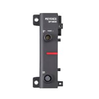
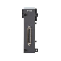
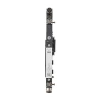
External Manifold Connection Unit
|
Model |
SP-ND25 |
|||
|
Image |
|
|||
|
Type |
External Manifold Connection Unit |
|||
|
D-sub connector |
Output connector |
D-sub (25-pin) socket |
||
|
Number of outputs |
24 |
|||
|
Output voltage |
Varies depending on the power voltage supplied to the communication unit *1 |
|||
|
Maximum load current |
100 mA/output *2 |
|||
|
Leakage current |
0.1 mA or less |
|||
|
Protection circuit |
Overcurrent protection circuit |
|||
|
Current consumption |
60 mA or less at 24 V *3 |
|||
|
Environmental resistance |
Enclosure rating |
IP40 (IEC 60529) |
||
|
Ambient temperature |
-5 to +50°C 23 to 122°F (no freezing) |
|||
|
Relative humidity |
Up to 85% RH (no condensation) |
|||
|
Vibration resistance |
10 to 500 Hz; Power spectral density: 0.204 G2/Hz; X, Y, and |
|||
|
Shock resistance |
100 m/s2 328.1 ft/s2 (10 G); 1000 times each for X, Y, and Z axes |
|||
|
Material |
PBT, PAR, POM, NBR, Iron nickel plating |
|||
|
Weight |
Approx. 130 g 4.59 oz |
|||
|
*1 The output voltage will be the power voltage supplied to the communication unit minus 3 V or more. |
||||
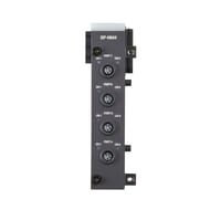
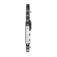
I/O Unit
|
Model |
SP-NM4 |
|||
|
Image |
|
|||
|
Type |
I/O Unit |
|||
|
I/O port |
Connector |
M8 (A-code) 4-pin, female; 4 ports |
||
|
Power supply capacity |
Per port: 180 mA; Total for 4 ports: 7.5 W *1 *2 |
|||
|
Protection circuit |
Reverse polarity protection circuit, Overcurrent protection circuit |
|||
|
Communication, I/O |
Switchable between CS-Link, control input, and control output |
|||
|
CS-Link |
Supported models |
CS-LxxPC/SP-Cxx |
||
|
Max. number of connected units |
CS-LxxPC: Up to 2 units per port; |
|||
|
Control input |
Input type |
PNP/NPN switchable |
||
|
Max. number of inputs |
Per port: 2; Total for 4 ports: 8 *3 |
|||
|
ON voltage |
PNP: 15 V or more, NPN: 6 V or less |
|||
|
OFF voltage |
PNP: 6 V or less, NPN: 15 V or more |
|||
|
Short-circuit current |
3 mA or less |
|||
|
Protection circuit |
Surge protection circuit |
|||
|
Control output |
Output format |
PNP/NPN switchable |
||
|
Max. number of outputs |
Per port: 2; Total for 4 ports: 8 *3 |
|||
|
Maximum load current |
100 mA (per output) |
|||
|
Residual voltage |
2.5 V or less |
|||
|
Leakage current |
0.1 mA or less |
|||
|
Protection circuit |
Surge protection circuit, Overcurrent protection circuit |
|||
|
Current consumption |
80 mA or less at 24 V *4 |
|||
|
Environmental resistance |
Enclosure rating |
IP65/IP67 (IEC 60529) |
||
|
Ambient temperature |
-5 to +50°C 23 to 122°F (no freezing) |
|||
|
Relative humidity |
Up to 85% RH (no condensation) |
|||
|
Vibration resistance |
10 to 500 Hz; Power spectral density: 0.204 G2/Hz; X, Y, and |
|||
|
Shock resistance |
100 m/s2 328.1 ft/s2 (10 G); 1000 times each for X, Y, and Z axes |
|||
|
Material |
PBT, PAR, POM, NBR, LCP |
|||
|
Weight |
Approx. 110 g 3.88 oz |
|||
|
*1 The voltage varies depending on the power voltage supplied to the communication unit. |
||||
Valve Unit 10 mm Single/Double
|
Model |
SP-VS10D4 |
SP-VS10D6 |
SP-VS10D7 |
SP-VD10D4 |
SP-VD10D6 |
SP-VD10D7 |
|||
|
Image |
|
|
|
|
|
|
|||
|
Type |
Valve unit |
||||||||
|
Valve size |
10 mm 0.39" |
||||||||
|
Valve type |
Single |
Double |
|||||||
|
Port size |
ø4 ø0.16" |
ø6 ø0.24" |
1/4" |
ø4 ø0.16" |
ø6 ø0.24" |
1/4" |
|||
|
Valve structure |
Elastomer seal |
||||||||
|
Manual operation |
Push-turn lock type (driver operation) |
||||||||
|
Supported fluids |
Air *1 |
||||||||
|
Fluid temperature |
-5 to +50°C 23 to 122°F (no freezing) |
||||||||
|
Flow rate characteristics |
400 L/min |
||||||||
|
Response time |
26 ms or less *3 |
||||||||
|
Maximum operating frequency |
5 Hz *4 |
||||||||
|
Operating pressure range |
With internal pilot |
0.2 to 0.8 MPa |
|||||||
|
With external pilot |
0 to 0.8 MPa *5 |
||||||||
|
Pressure resistance |
1.0 MPa |
||||||||
|
Sensor connection port |
Connector |
M8 (A-code) 4-pin, female |
|||||||
|
Power supply capacity |
200 mA *6 |
||||||||
|
Protection circuit |
Overcurrent protection circuit |
||||||||
|
Communication/input |
Switchable between CS-Link and control input |
||||||||
|
CS-Link |
Supported models |
CS-LxxPC/SP-Cxx |
|||||||
|
Number of connectable devices |
CS-LxxPC: Up to 2 units; SP-Cxx: Up to 2 units *7 |
||||||||
|
Control input |
Input type |
PNP/NPN switchable |
|||||||
|
Max. number of inputs |
2 *7 |
||||||||
|
ON voltage |
PNP: 15 V or more, NPN: 6 V or less |
||||||||
|
OFF voltage |
PNP: 6 V or less, NPN: 15 V or more |
||||||||
|
Short-circuit current |
3 mA or less |
||||||||
|
Protection circuit |
Surge protection circuit |
||||||||
|
Current consumption |
Without valve operation: 20 mA or less at 24 V; |
||||||||
|
Environmental resistance |
Enclosure rating |
IP65/IP67 (IEC 60529) |
|||||||
|
Ambient temperature |
-5 to +50°C 23 to 122°F (no freezing) |
||||||||
|
Relative humidity |
Up to 85% RH (no condensation) |
||||||||
|
Vibration resistance |
10 to 500 Hz; Power spectral density: 0.204 G2/Hz; X, Y, and Z directions |
||||||||
|
Shock resistance |
100 m/s2 328.1 ft/s2 (10 G); 1000 times each for X, Y, and Z axes |
||||||||
|
Material |
Flow path |
Polyamide, POM, Aluminum alloy, FKM, HNBR, NBR, Nickel-plated brass / Brass (closed center, exhaust center, and pressure center types only) |
|||||||
|
Non-flow path |
Polyamide, PAR, POM, HNBR, NBR, Aluminum alloy, Zinc-nickel plating, SUS304 |
||||||||
|
Weight |
Approx. 120 g |
Approx. 130 g |
|||||||
|
*1 If air with a low dew point is used as the operating fluid, deterioration of the lubrication characteristics inside the device may affect the reliability (service life) of the equipment. |
|||||||||
Valve Unit 10 mm Closed center/Exhaust center
|
Model |
SP-VC10D4 |
SP-VC10D6 |
SP-VC10D7 |
SP-VE10D4 |
SP-VE10D6 |
SP-VE10D7 |
|||
|
Image |
|
|
|
|
|
|
|||
|
Type |
Valve unit |
||||||||
|
Valve size |
10 mm 0.39" |
||||||||
|
Valve type |
Closed center |
Exhaust center |
|||||||
|
Port size |
ø4 ø0.16" |
ø6 ø0.24" |
1/4" |
ø4 ø0.16" |
ø6 ø0.24" |
1/4" |
|||
|
Valve structure |
Elastomer seal |
||||||||
|
Manual operation |
Push-turn lock type (driver operation) |
||||||||
|
Supported fluids |
Air *1 |
||||||||
|
Fluid temperature |
-5 to +50°C 23 to 122°F (no freezing) |
||||||||
|
Flow rate characteristics |
360 L/min |
340 L/min |
|||||||
|
Response time |
36 ms or less *3 |
||||||||
|
Maximum operating frequency |
3 Hz *4 |
||||||||
|
Operating pressure range |
With internal pilot |
0.3 to 0.8 MPa |
|||||||
|
With external pilot |
0 to 0.8 MPa *5 |
||||||||
|
Pressure resistance |
1.0 MPa |
||||||||
|
Sensor connection port |
Connector |
M8 (A-code) 4-pin, female |
|||||||
|
Power supply capacity |
200 mA *6 |
||||||||
|
Protection circuit |
Overcurrent protection circuit |
||||||||
|
Communication/input |
Switchable between CS-Link and control input |
||||||||
|
CS-Link |
Supported models |
CS-LxxPC/SP-Cxx |
|||||||
|
Number of connectable devices |
CS-LxxPC: Up to 2 units; SP-Cxx: Up to 2 units *7 |
||||||||
|
Control input |
Input type |
PNP/NPN switchable |
|||||||
|
Max. number of inputs |
2 *7 |
||||||||
|
ON voltage |
PNP: 15 V or more, NPN: 6 V or less |
||||||||
|
OFF voltage |
PNP: 6 V or less, NPN: 15 V or more |
||||||||
|
Short-circuit current |
3 mA or less |
||||||||
|
Protection circuit |
Surge protection circuit |
||||||||
|
Current consumption |
Without valve operation: 20 mA or less at 24 V; |
||||||||
|
Environmental resistance |
Enclosure rating |
IP65/IP67 (IEC 60529) |
|||||||
|
Ambient temperature |
-5 to +50°C 23 to 122°F (no freezing) |
||||||||
|
Relative humidity |
Up to 85% RH (no condensation) |
||||||||
|
Vibration resistance |
10 to 500 Hz; Power spectral density: 0.204 G2/Hz; X, Y, and Z directions |
||||||||
|
Shock resistance |
100 m/s2 328.1 ft/s2 (10 G); 1000 times each for X, Y, and Z axes |
||||||||
|
Material |
Flow path |
Polyamide, POM, Aluminum alloy, FKM, HNBR, NBR, Nickel-plated brass / Brass (closed center, exhaust center, and pressure center types only) |
|||||||
|
Non-flow path |
Polyamide, PAR, POM, HNBR, NBR, Aluminum alloy, Zinc-nickel plating, SUS304 |
||||||||
|
Weight |
Approx. 130 g |
||||||||
|
*1 If air with a low dew point is used as the operating fluid, deterioration of the lubrication characteristics inside the device may affect the reliability (service life) of the equipment. |
|||||||||
Valve Unit 10 mm Pressure center/Dual 3-port (NC/NC)
|
Model |
SP-VP10D4 |
SP-VP10D6 |
SP-VP10D7 |
SP-VT10D4 |
SP-VT10D6 |
SP-VT10D7 |
|||
|
Image |
|
|
|
|
|
|
|||
|
Type |
Valve unit |
||||||||
|
Valve size |
10 mm 0.39" |
||||||||
|
Valve type |
Pressure center |
Dual 3-port (NC/NC) |
|||||||
|
Port size |
ø4 ø0.16" |
ø6 ø0.24" |
1/4" |
ø4 ø0.16" |
ø6 ø0.24" |
1/4" |
|||
|
Valve structure |
Elastomer seal |
||||||||
|
Manual operation |
Push-turn lock type (driver operation) |
||||||||
|
Supported fluids |
Air *1 |
||||||||
|
Fluid temperature |
-5 to +50°C 23 to 122°F (no freezing) |
||||||||
|
Flow rate characteristics |
380 L/min |
330 L/min |
|||||||
|
Response time |
36 ms or less *3 |
||||||||
|
Maximum operating frequency |
3 Hz *4 |
||||||||
|
Operating pressure range |
With internal pilot |
0.3 to 0.8 MPa |
0.25 to 0.8 MPa |
||||||
|
With external pilot |
0 to 0.8 MPa *5 |
0.2 to 0.8 MPa *5 |
|||||||
|
Pressure resistance |
1.0 MPa |
||||||||
|
Sensor connection port |
Connector |
M8 (A-code) 4-pin, female |
|||||||
|
Power supply capacity |
200 mA *6 |
||||||||
|
Protection circuit |
Overcurrent protection circuit |
||||||||
|
Communication/input |
Switchable between CS-Link and control input |
||||||||
|
CS-Link |
Supported models |
CS-LxxPC/SP-Cxx |
|||||||
|
Number of connectable devices |
CS-LxxPC: Up to 2 units; SP-Cxx: Up to 2 units *7 |
||||||||
|
Control input |
Input type |
PNP/NPN switchable |
|||||||
|
Max. number of inputs |
2 *7 |
||||||||
|
ON voltage |
PNP: 15 V or more, NPN: 6 V or less |
||||||||
|
OFF voltage |
PNP: 6 V or less, NPN: 15 V or more |
||||||||
|
Short-circuit current |
3 mA or less |
||||||||
|
Protection circuit |
Surge protection circuit |
||||||||
|
Current consumption |
Without valve operation: 20 mA or less at 24 V; |
||||||||
|
Environmental resistance |
Enclosure rating |
IP65/IP67 (IEC 60529) |
|||||||
|
Ambient temperature |
-5 to +50°C 23 to 122°F (no freezing) |
||||||||
|
Relative humidity |
Up to 85% RH (no condensation) |
||||||||
|
Vibration resistance |
10 to 500 Hz; Power spectral density: 0.204 G2/Hz; X, Y, and Z directions |
||||||||
|
Shock resistance |
100 m/s2 328.1 ft/s2 (10 G); 1000 times each for X, Y, and Z axes |
||||||||
|
Material |
Flow path |
Polyamide, POM, Aluminum alloy, FKM, HNBR, NBR, Nickel-plated brass / Brass (closed center, exhaust center, and pressure center types only) |
|||||||
|
Non-flow path |
Polyamide, PAR, POM, HNBR, NBR, Aluminum alloy, Zinc-nickel plating, SUS304 |
||||||||
|
Weight |
Approx. 130 g |
||||||||
|
*1 If air with a low dew point is used as the operating fluid, deterioration of the lubrication characteristics inside the device may affect the reliability (service life) of the equipment. |
|||||||||
Valve Unit 14 mm Single/Double
|
Model |
SP-VS14D6 |
SP-VS14D7 |
SP-VS14D8 |
SP-VD14D6 |
SP-VD14D7 |
SP-VD14D8 |
|||
|
Image |
|
|
|
|
|
|
|||
|
Type |
Valve unit |
||||||||
|
Valve size |
14 mm 0.55" |
||||||||
|
Valve type |
Single |
Double |
|||||||
|
Port size |
ø6 ø0.24" |
1/4" |
ø8 ø0.31" |
ø6 ø0.24" |
1/4" |
ø8 ø0.31" |
|||
|
Valve structure |
Elastomer seal |
||||||||
|
Manual operation |
Push-turn lock type (driver operation) |
||||||||
|
Supported fluids |
Air *1 |
||||||||
|
Fluid temperature |
-5 to +50°C 23 to 122°F (no freezing) |
||||||||
|
Flow rate characteristics |
650 L/min |
||||||||
|
Response time |
30 ms or less *3 |
||||||||
|
Maximum operating frequency |
5 Hz *4 |
||||||||
|
Operating pressure range |
With internal pilot |
0.2 to 0.8 Mpa |
|||||||
|
With external pilot |
0 to 0.8 MPa *5 |
||||||||
|
Pressure resistance |
1.0 MPa |
||||||||
|
Sensor connection port |
Connector |
M8 (A-code) 4-pin, female |
|||||||
|
Power supply capacity |
200 mA *6 |
||||||||
|
Protection circuit |
Overcurrent protection circuit |
||||||||
|
Communication/input |
Switchable between CS-Link and control input |
||||||||
|
CS-Link |
Supported models |
CS-LxxPC/SP-Cxx |
|||||||
|
Number of connectable devices |
CS-LxxPC: Up to 2 units; SP-Cxx: Up to 2 units *7 |
||||||||
|
Control input |
Input type |
PNP/NPN switchable |
|||||||
|
Max. number of inputs |
2 *7 |
||||||||
|
ON voltage |
PNP: 15 V or more, NPN: 6 V or less |
||||||||
|
OFF voltage |
PNP: 6 V or less, NPN: 15 V or more |
||||||||
|
Short-circuit current |
3 mA or less |
||||||||
|
Protection circuit |
Surge protection circuit |
||||||||
|
Current consumption |
Without valve operation: 20 mA or less at 24 V; |
||||||||
|
Environmental resistance |
Enclosure rating |
IP65/IP67 (IEC 60529) |
|||||||
|
Ambient temperature |
-5 to +50°C 23 to 122°F (no freezing) |
||||||||
|
Relative humidity |
Up to 85% RH (no condensation) |
||||||||
|
Vibration resistance |
10 to 500 Hz; Power spectral density: 0.204 G2/Hz; X, Y, and Z directions |
||||||||
|
Shock resistance |
100 m/s2 328.1 ft/s2 (10 G); 1000 times each for X, Y, and Z axes |
||||||||
|
Material |
Flow path |
Polyamide, POM, Aluminum alloy, FKM, HNBR, NBR, Nickel-plated brass / Brass (closed center, exhaust center, and pressure center types only) |
|||||||
|
Non-flow path |
Polyamide, PAR, POM, HNBR, NBR, Aluminum alloy, Zinc-nickel plating, SUS304 |
||||||||
|
Weight |
Approx. 160 g |
Approx. 170 g |
|||||||
|
*1 If air with a low dew point is used as the operating fluid, deterioration of the lubrication characteristics inside the device may affect the reliability (service life) of the equipment. |
|||||||||
Valve Unit 14 mm Closed center/Exhaust center
|
Model |
SP-VC14D6 |
SP-VC14D7 |
SP-VC14D8 |
SP-VE14D6 |
SP-VE14D7 |
SP-VE14D8 |
|||
|
Image |
|
|
|
|
|
|
|||
|
Type |
Valve unit |
||||||||
|
Valve size |
14 mm 0.55" |
||||||||
|
Valve type |
Closed center |
Exhaust center |
|||||||
|
Port size |
ø6 ø0.24" |
1/4" |
ø8 ø0.31" |
ø6 ø0.24" |
1/4" |
ø8 ø0.31" |
|||
|
Valve structure |
Elastomer seal |
||||||||
|
Manual operation |
Push-turn lock type (driver operation) |
||||||||
|
Supported fluids |
Air *1 |
||||||||
|
Fluid temperature |
-5 to +50°C 23 to 122°F (no freezing) |
||||||||
|
Flow rate characteristics |
470 L/min |
||||||||
|
Response time |
40 ms or less *3 |
||||||||
|
Maximum operating frequency |
3 Hz *4 |
||||||||
|
Operating pressure range |
With internal pilot |
0.3 to 0.8 MPa |
|||||||
|
With external pilot |
0 to 0.8 MPa *5 |
||||||||
|
Pressure resistance |
1.0 MPa |
||||||||
|
Sensor connection port |
Connector |
M8 (A-code) 4-pin, female |
|||||||
|
Power supply capacity |
200 mA *6 |
||||||||
|
Protection circuit |
Overcurrent protection circuit |
||||||||
|
Communication/input |
Switchable between CS-Link and control input |
||||||||
|
CS-Link |
Supported models |
CS-LxxPC/SP-Cxx |
|||||||
|
Number of connectable devices |
CS-LxxPC: Up to 2 units; SP-Cxx: Up to 2 units *7 |
||||||||
|
Control input |
Input type |
PNP/NPN switchable |
|||||||
|
Max. number of inputs |
2 *7 |
||||||||
|
ON voltage |
PNP: 15 V or more, NPN: 6 V or less |
||||||||
|
OFF voltage |
PNP: 6 V or less, NPN: 15 V or more |
||||||||
|
Short-circuit current |
3 mA or less |
||||||||
|
Protection circuit |
Surge protection circuit |
||||||||
|
Current consumption |
Without valve operation: 20 mA or less at 24 V; |
||||||||
|
Environmental resistance |
Enclosure rating |
IP65/IP67 (IEC 60529) |
|||||||
|
Ambient temperature |
-5 to +50°C 23 to 122°F (no freezing) |
||||||||
|
Relative humidity |
Up to 85% RH (no condensation) |
||||||||
|
Vibration resistance |
10 to 500 Hz; Power spectral density: 0.204 G2/Hz; X, Y, and Z directions |
||||||||
|
Shock resistance |
100 m/s2 328.1 ft/s2 (10 G); 1000 times each for X, Y, and Z axes |
||||||||
|
Material |
Flow path |
Polyamide, POM, Aluminum alloy, FKM, HNBR, NBR, Nickel-plated brass / Brass (closed center, exhaust center, and pressure center types only) |
|||||||
|
Non-flow path |
Polyamide, PAR, POM, HNBR, NBR, Aluminum alloy, Zinc-nickel plating, SUS304 |
||||||||
|
Weight |
Approx. 170 g |
||||||||
|
*1 If air with a low dew point is used as the operating fluid, deterioration of the lubrication characteristics inside the device may affect the reliability (service life) of the equipment. |
|||||||||
Valve Unit 14 mm Pressure center/Dual 3-port (NC/NC)
|
Model |
SP-VP14D6 |
SP-VP14D7 |
SP-VP14D8 |
SP-VT14D6 |
SP-VT14D7 |
SP-VT14D8 |
|||
|
Image |
|
|
|
|
|
|
|||
|
Type |
Valve unit |
||||||||
|
Valve size |
14 mm 0.55" |
||||||||
|
Valve type |
Pressure center |
Dual 3-port (NC/NC) |
|||||||
|
Port size |
ø6 ø0.24" |
1/4" |
ø8 ø0.31" |
ø6 ø0.24" |
1/4" |
ø8 ø0.31" |
|||
|
Valve structure |
Elastomer seal |
||||||||
|
Manual operation |
Push-turn lock type (driver operation) |
||||||||
|
Supported fluids |
Air *1 |
||||||||
|
Fluid temperature |
-5 to +50°C 23 to 122°F (no freezing) |
||||||||
|
Flow rate characteristics |
650 L/min |
580 L/min |
|||||||
|
Response time |
40 ms or less *3 |
||||||||
|
Maximum operating frequency |
3 Hz *4 |
||||||||
|
Operating pressure range |
With internal pilot |
0.3 to 0.8 MPa |
0.25 to 0.8 MPa |
||||||
|
With external pilot |
0 to 0.8 MPa *5 |
0.2 to 0.8 MPa *5 |
|||||||
|
Pressure resistance |
1.0 MPa |
||||||||
|
Sensor connection port |
Connector |
M8 (A-code) 4-pin, female |
|||||||
|
Power supply capacity |
200 mA *6 |
||||||||
|
Protection circuit |
Overcurrent protection circuit |
||||||||
|
Communication/input |
Switchable between CS-Link and control input |
||||||||
|
CS-Link |
Supported models |
CS-LxxPC/SP-Cxx |
|||||||
|
Number of connectable devices |
CS-LxxPC: Up to 2 units; SP-Cxx: Up to 2 units *7 |
||||||||
|
Control input |
Input type |
PNP/NPN switchable |
|||||||
|
Max. number of inputs |
2 *7 |
||||||||
|
ON voltage |
PNP: 15 V or more, NPN: 6 V or less |
||||||||
|
OFF voltage |
PNP: 6 V or less, NPN: 15 V or more |
||||||||
|
Short-circuit current |
3 mA or less |
||||||||
|
Protection circuit |
Surge protection circuit |
||||||||
|
Current consumption |
Without valve operation: 20 mA or less at 24 V; |
||||||||
|
Environmental resistance |
Enclosure rating |
IP65/IP67 (IEC 60529) |
|||||||
|
Ambient temperature |
-5 to +50°C 23 to 122°F (no freezing) |
||||||||
|
Relative humidity |
Up to 85% RH (no condensation) |
||||||||
|
Vibration resistance |
10 to 500 Hz; Power spectral density: 0.204 G2/Hz; X, Y, and Z directions |
||||||||
|
Shock resistance |
100 m/s2 328.1 ft/s2 (10 G); 1000 times each for X, Y, and Z axes |
||||||||
|
Material |
Flow path |
Polyamide, POM, Aluminum alloy, FKM, HNBR, NBR, Nickel-plated brass / Brass (closed center, exhaust center, and pressure center types only) |
|||||||
|
Non-flow path |
Polyamide, PAR, POM, HNBR, NBR, Aluminum alloy, Zinc-nickel plating, SUS304 |
||||||||
|
Weight |
Approx. 170 g |
Approx. 160 g |
|||||||
|
*1 If air with a low dew point is used as the operating fluid, deterioration of the lubrication characteristics inside the device may affect the reliability (service life) of the equipment. |
|||||||||
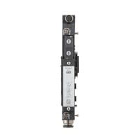
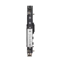
Supply/Exhaust Unit
|
Model |
SP-VF8L |
SP-VF9L |
SP-VF10L |
SP-VF8M |
SP-VF9M |
SP-VF10M |
|||
|
Image |
|
|
|
|
|
|
|||
|
Type |
Supply/exhaust unit |
||||||||
|
Connection position within valve module |
Left side |
Right side/intermediate |
|||||||
|
Supply/exhaust port connection bore diameter |
ø8 ø0.31" |
3/8" |
ø10 ø0.39" |
ø8 ø0.31" |
3/8" |
ø10 ø0.39" |
|||
|
Operating fluid |
Air |
||||||||
|
Fluid temperature |
-5 to +50°C 23 to 122°F (no freezing) |
||||||||
|
Pilot method |
Internal, External *1 |
||||||||
|
Pilot exhaust method |
Collective exhaust via end unit |
||||||||
|
Pressure resistance |
1.0 MPa |
||||||||
|
Environmental resistance |
Enclosure rating |
IP65/IP67 (IEC 60529) |
|||||||
|
Ambient temperature |
-5 to +50°C 23 to 122°F (no freezing) |
||||||||
|
Relative humidity |
Up to 85% RH (no condensation) |
||||||||
|
Vibration resistance |
10 to 500 Hz; Power spectral density: 0.204 G2/Hz; X, Y, and Z directions |
||||||||
|
Shock resistance |
100 m/s2 328.1 ft/s2 (10 G); 1000 times each for X, Y, and Z axes |
||||||||
|
Material |
Flow path |
Polyamide, HNBR, NBR, Nickel-plated brass |
|||||||
|
Non-flow path |
Polyamide, PBT, POM, HNBR, NBR, Nickel-plated brass, Zinc-nickel plating, SUS304 |
||||||||
|
Weight |
Approx. 250 g 8.83 oz |
Approx. 210 g 7.41 oz |
|||||||
|
*1 Use with an external pilot system is possible by installing an optional supply/exhaust unit with external pilot functionality. |
|||||||||
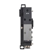
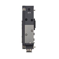
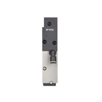
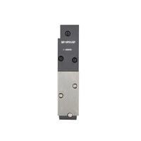
Optional supply/exhaust unit
|
Model |
SP-VF02 |
SP-VF01AP |
SP-VF02AP |
|||
|
Image |
|
|
|
|||
|
Pilot method |
External |
Internal |
External |
|||
|
Pilot exhaust method |
Collective exhaust via end unit |
|||||
|
External pilot port |
Connection bore diameter |
ø4 ø0.16" *1 |
- |
ø4 ø0.16" *1 |
||
|
Pressure resistance |
1.0 MPa *1 |
|||||
|
Pressure sensor |
None |
Available |
||||
|
Pressure sensor |
Rated pressure |
- |
0 to 0.8 MPa |
|||
|
Measurement accuracy |
±2.0% of F.S. *3 |
|||||
|
Repeatability |
±0.4% of F.S. *3 |
|||||
|
Response time |
50 ms |
|||||
|
Current consumption |
10 mA or less at 24 V |
|||||
|
Material |
Polyamide, PBT, PAR *2 , HNBR, NBR, SUS304, SUSXM7 |
|||||
|
Weight |
Approx. 40 g 1.41 oz |
Approx. 45 g 1.59 oz |
||||
|
*1 The minimum pilot pressure required for pilot valve operation varies depending on the valve type. Refer to the valve unit specifications. |
||||||