CMM (Coordinate Measuring Machine)
The Significance of Final Inspections on Parts and Assemblies
Key Takeaways
- Final inspection standardizes quality across supply chains, catching defects missed earlier.
- GD&T (true position, flatness, perpendicularity, etc.) specifies assembly‑critical geometric requirements.
- CMMs are the preferred tool for GD&T: they capture 3D coordinates and verify positional tolerances.
- Add GD&T to CAD to remove ambiguity, reduce rework, and ensure proper assembly fit‑up.
- Portable/handheld CMMs enable fast on‑site final checks, speeding throughput and traceability.
Quality control is critical in the rapidly moving manufacturing industry that cycles through millions of products daily. Before any product reaches the hands of a consumer, every part of the supply chain has to be checked to ensure specifications and quality are met. There are inspections throughout machining and the supply chain, but there’s one final inspection where technicians check the entire product before it heads out.
To do this, inspectors must follow specific standards and processes to ensure consistency across the board. Let’s dive into the final inspection process and how it works.
Why is the Final Inspection Process Necessary?
Before a consumer uses a product, the product often cycles through a supply chain of multiple locations, machines, operators, and environments. Regardless of how many changes the product goes through, consistency and quality control cannot be compromised – this is where the final inspection process comes in.
Although there are inspections throughout the supply chain, like in-process inspections, these inspections don’t always capture problems. Each manufacturing plant is focused on its role in the chain, so the operator inspecting may miss a defect because the focus is only on one area. Additionally, since these plants have different standards, the inspection process in manufacturing can easily be prone to human error because the viewing is opinion-based.
The final inspection process is standardization after the in-process inspections. It is the confirmation that even through a supply chain with uncontrollable variables, the product will be put out at a consistent measurement, appearance, and dimension as the rest of the products of its type.
We’re here to provide you with more details.
Reach out today!

What Does the Final Inspection Process Entail?
During the final inspection in manufacturing, technicians inspect a product's characteristics, including defects with labels, contaminants, damage, polarity, wire placement, and cosmetic appearance. The inspectors also review key measurements to ensure it was assembled correctly and is within its correct tolerance.
What Key Measurements Help With Inspection?
When inspecting, key measurements are dimensional measurements and GD&T inspections.
The product type determines what critical measurements will be used for inspecting. Typical dimensional measurements like hole diameter, distance, and angle don’t always have a GD&T aspect to their dimension. However, GD&T is necessary for the final inspection process of products that comprise multiple parts assembled together. GD&T checks to make sure the fit-up of the assembly is correct and to spec.
What is GD&T Inspection?
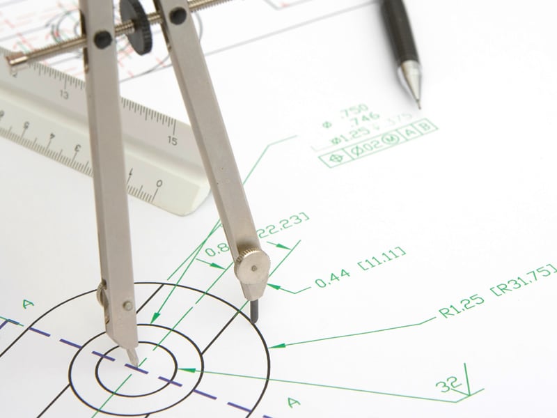
GD&T, which stands for geometric dimensioning and tolerancing, was created so there would be a more detailed understanding of how a product should be assembled so the production line could move faster.
GD&T follows the use of datums – a point, line, or plane that exists in the geometric conceptual space (Datum Reference Frame/DRF) and is identified as the start of a measurement. This practice is a standardized method by the American Society of Mechanical Engineers (ASME) that utilizes geometric symbols in CAD models for manufacturers, engineers, and inspectors to have a common language.
Contact us to learn more about how our advanced technology can help take your business to the next level.
Contact Us
Why is GD&T Needed?
When products are designed, the first step is for the engineer to create a CAD model to show manufacturers how the product should look. However, these illustrations sometimes can’t fully grasp how a product fits together or give details on how necessary an exact measurement is. GD&T is a way for engineers to specify the true position – meaning how much the dimensions can deviate in a tolerance zone while still being assembled correctly. It also gives manufacturers geometric information about how a part will align with other parts in the complete product.
GD&T Examples
GD&T covers over ten types of features, including:
- Straightness
- Flatness
- Circularity
- Line profile
- Surface profile
- Angularity
- Perpendicularity
- Parallelism
- Position
- Concentricity
- Symmetry
- Circular runout
- Total runout
Let’s review some examples of how these GD&T features play out in the inspection process in manufacturing.
GD&T Example 1:
A manufacturer receives a CAD model specifying metal desks that require four holes 15 cm apart. However, the 15 cm apart doesn’t give GD&T information.
The manufacturer is unsure of the relationship between the holes and what plane they are 15 cm apart on. The manufacturer chooses where they think is best and sends it through the supply chain. The inspector then views the part and sees that the holes are 15 cm apart, so the desk passes the inspection. However, when the desk ends up at the plant where the desk is assembled using the holes, the manufacturers cannot put it together because the holes don’t align.
In this example, the engineer could have included true position, concentricity, parallelism, and/or perpendicularity to specify where the holes should be.
- Adding the true position would identify where the hole should be added in connection to a datum on the desk,
- including concentricity would give a center reference point for the holes to be aligned against and,
- putting parallelism or perpendicularity on the model would identify the holes' relationship with each other.
GD&T Example 2:
A manufacturer receives a CAD model for a table that says the metal chair’s leg tolerance is 2mm to 3mm. However, the tolerance gives no GD&T information signifying how the table will be assembled.
The manufacturer produces chair legs between these tolerances and sends them through the supply chain. When the operator inspects the chair with the legs within these tolerances, the inspector immediately passes it through without evaluating the usefulness of the chair.
In this case, the engineer should have added GD&T for additional information.
- GD&T parallelism symbol to signify that the legs must be parallel to one another,
- perpendicularity to identify that the legs must be perpendicular to the cushion or
- positioning information to mark the relationship the legs have with each other.
Discover more about this product.
Click here to book your demo.

How Do I Measure GD&T?
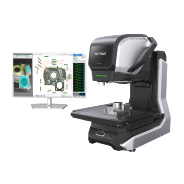
Some GD&T features can be measured by appearance, but most are best measured with a coordinate measurement machine (CMM) because it can capture the dimensions for analysis. CMMs come in different styles, like handheld, gantry, bridge, and cantilever.
Depending on the CMM, these tools will achieve ranges of GD&T features. But generally, these tools can inspect parallelism, angularity, flatness, perpendicularity, and hole distance. Specialized tools that incorporate additional software can analyze data and inspect all GD&T features.
Getting the Best Results for the Final Inspection Process
Regardless of the industry or product type, the final inspection process is necessary to keep quality control. Without the final inspection in manufacturing, it would be a gamble for a manufacturing plant every time they send out a product – with them only hoping that the inspection process was done correctly along the way.
The final inspection process can be done even more precisely when engineers add GD&T information for manufacturers and inspectors to follow. By adding GD&T features like true position, parallelism, perpendicularity, and others, the inspection process has less ambiguity and better quality control.
Do You Need a CMM for Your GD&T Final Inspection Process?
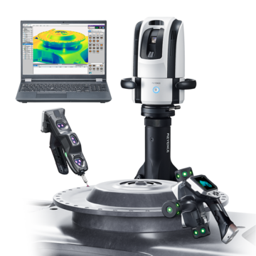
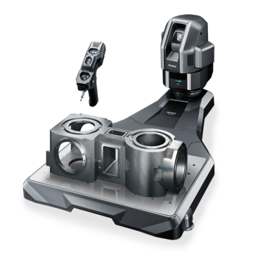
At KEYENCE, we offer two handheld CMMs, the XM and WM, that analyze GD&T features in seconds. We know the final inspection in manufacturing is tedious, and sometimes you need direction – that’s why we made our CMMs user-friendly, so you don’t need training to start using them. Want to see it in action? Contact us today for a free demo.
Contact us to learn more about how our advanced technology can help take your business to the next level.
Contact Us
Related Downloads
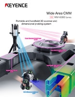
Brochure for the WM-6000 series Wide-Area CMM. A portable setup with a wireless handheld probe that enables users measure large parts and equipment.

![WM-6000 series Measurement / Application Examples [Fabrication Application Examples]](/img/asset/AS_116822_L.jpg)
![WM-6000 series Measurement / Application Examples [In-Machine Measurement Examples]](/img/asset/AS_116821_L.jpg)
![WM-6000 series Measurement / Application Examples [System Versatility Examples]](/img/asset/AS_116820_L.jpg)
