Surface Finish Symbols and Chart: How to Read and Specify Surface Finish on a Drawing
A surface finish specification on a drawing tells a machinist what texture a surface must have, how it is produced, and how it will be checked. It is written as a symbol, a roughness parameter such as Ra, a limit value in micrometers (µm) or microinches (µin), and sometimes a lay direction. This guide explains how to read surface finish symbols, how to use a surface finish chart of Ra values and N-grades, and how to verify the callout on the finished part.
Key Takeaways
- A surface finish callout combines a symbol, a roughness parameter, a limit value, and, when they matter, a production method and lay direction.
- There are three basic surface finish symbols: any process allowed, material removal required, and material removal prohibited.
- ISO roughness grades N1 to N12 map to fixed Ra values. For example, N8 equals Ra 3.2 µm (125 µin) and N6 equals Ra 0.8 µm (32 µin).
- 1 µm equals about 39.4 µin. Older US drawings often use µin and the term RMS, which is about 1.11 times Ra on a sinusoidal profile.
- Appearance finishes such as bead blasted, brushed, and anodized are usually specified by process or reference sample, not by Ra alone.
- Surface finish measurement should use the same parameter, cutoff, and trace direction the drawing calls for.
What Does a Surface Finish Specification Include?
A surface finish specification is more than a single number. Each element answers a different question for the person making or inspecting the part, and leaving one out is a common source of disputes between a supplier and a customer.
| Element | What it states | Example |
|---|---|---|
|
Symbol
|
What it states
Whether machining is required or prohibited
|
Example
Basic symbol with a bar
|
|
Parameter
|
What it states
Which roughness measure applies
|
Example
Ra or Rz
|
|
Limit value
|
What it states
The maximum allowed roughness, or a range
|
Example
1.6 µm (63 µin)
|
|
Production method
|
What it states
How the surface is made, if it matters
|
Example
Ground
|
|
Lay
|
What it states
The direction of the dominant pattern
|
Example
⊥ (perpendicular)
|
|
Cutoff / sampling length
|
What it states
The filter used when measuring
|
Example
0.8 mm
|
A callout such as "Ra 1.6" is shorthand for this whole set, with the rest implied by the drawing standard. Roughness is the measurable part of surface finish. For what a roughness value reveals about wear, sealing, and process stability, see what surface roughness tells you about a part.
How Do You Read Surface Finish Symbols?
Every surface finish symbol starts from the same basic shape, a check-mark-style line drawn against the surface. Small additions change what the symbol demands about how the surface was produced.
| Symbol variant | What it means | When it is used |
|---|---|---|
|
Basic symbol
|
What it means
A surface texture requirement applies. The process is not specified.
|
When it is used
Any process may produce the surface
|
|
Basic symbol with a horizontal bar
|
What it means
Material removal by machining is required
|
When it is used
Surfaces that must be cut, ground, or otherwise machined
|
|
Basic symbol with a circle
|
What it means
Material removal is prohibited
|
When it is used
Surfaces left as cast, forged, or rolled
|
Requirements are written around the symbol. The parameter and limit value sit with the symbol, and optional entries for production method, lay, and machining allowance sit nearby. Their exact positions differ between ISO and ASME Y14.36 drawings, so read the standard named in the title block.
The standard itself matters. ISO 21920-1 replaced ISO 1302 and updated how surface texture requirements are indicated, while US drawings commonly follow ASME Y14.36. Older drawings keep the rules they were drawn under, so confirm which edition applies before interpreting an unfamiliar callout.
What Do Lay Symbols Mean?
Lay is the direction of the dominant surface pattern, and it matters because a surface can seal or wear differently along and across its tool marks. A lay symbol on the callout tells the maker which pattern to produce.
| Symbol | Lay direction | Example |
|---|---|---|
|
=
|
Lay direction
Parallel to the boundary line of the surface
|
Example
Depends on tool path
|
|
⊥
|
Lay direction
Perpendicular to the boundary line
|
Example
Depends on tool path
|
|
X
|
Lay direction
Crossed in two slanted directions
|
Example
Honed surfaces
|
|
M
|
Lay direction
Multidirectional
|
Example
Lapped surfaces
|
|
C
|
Lay direction
Approximately circular around the center
|
Example
Face-turned surfaces
|
|
R
|
Lay direction
Approximately radial from the center
|
Example
Depends on tool path
|
|
P
|
Lay direction
Particulate, non-directional, or protuberant
|
Example
Bead-blasted or EDM surfaces
|
Surface Finish Chart: Ra Values and N-Grades
ISO roughness grades N1 to N12 each stand for one standard Ra value. They appear on older metric drawings and in some CAD title blocks, and they are the quickest way to translate a grade into a number. The chart below shows each grade with its Ra in both unit systems and a common use.
| ISO grade | Ra (µm) | Ra (µin) | Common use |
|---|---|---|---|
|
N12
|
Ra (µm)
50
|
Ra (µin)
2,000
|
Common use
As-cast or flame-cut, non-functional surfaces
|
|
N11
|
Ra (µm)
25
|
Ra (µin)
1,000
|
Common use
Rough, non-critical surfaces
|
|
N10
|
Ra (µm)
12.5
|
Ra (µin)
500
|
Common use
Rough machining, non-critical
|
|
N9
|
Ra (µm)
6.3
|
Ra (µin)
250
|
Common use
Coarse machining, non-mating
|
|
N8
|
Ra (µm)
3.2
|
Ra (µin)
125
|
Common use
General machined surfaces
|
|
N7
|
Ra (µm)
1.6
|
Ra (µin)
63
|
Common use
Fine machining, close-fitting parts
|
|
N6
|
Ra (µm)
0.8
|
Ra (µin)
32
|
Common use
Sealing and bearing surfaces
|
|
N5
|
Ra (µm)
0.4
|
Ra (µin)
16
|
Common use
Ground surfaces, precision fits
|
|
N4
|
Ra (µm)
0.2
|
Ra (µin)
8
|
Common use
Fine-ground, honed, or lapped surfaces
|
|
N3
|
Ra (µm)
0.1
|
Ra (µin)
4
|
Common use
Lapped, high-precision sliding surfaces
|
|
N2
|
Ra (µm)
0.05
|
Ra (µin)
2
|
Common use
Polished or superfinished surfaces
|
|
N1
|
Ra (µm)
0.025
|
Ra (µin)
1
|
Common use
Gauge-grade and optical-grade surfaces
|
The "common use" column reflects typical practice, not a standard. The function of the part decides the right grade. Many shops treat 3.2 µm (125 µin) as the default for general machined surfaces, and every step finer adds machining time, so specify only the finish the part needs.
How Do You Convert µm to µin, and What Does RMS Mean?
Multiply micrometers by 39.37 to get microinches. That puts 1.6 µm at 63 µin and 0.8 µm at about 31.5 µin, which drawings conventionally round to 32 µin. Going the other way, divide microinches by 39.37.
RMS on an older US drawing means root mean square roughness, now called Rq. On a sinusoidal profile Rq is about 1.11 times Ra, so a 32 µin RMS callout corresponds to roughly 29 µin Ra. In practice, many shops read RMS and Ra as interchangeable. If the tolerance is tight, confirm which parameter the designer intended, because modern instruments report Ra by default.
How Do You Choose the Right Surface Finish Specification?
Start from what the surface has to do, then pick the coarsest finish that does it. A finer finish is not automatically better, as it raises cost, and some sliding surfaces need small valleys to hold lubricant.
- Non-functional or as-produced surfaces: use the "material removal prohibited" symbol, or a coarse general limit such as 3.2 µm (125 µin).
- Mating and press-fit surfaces: specify a finer value and check the lay, since the contact pattern matters.
- Sealing and bearing surfaces: these are often held to 0.8 µm (32 µin) or finer, and dynamic seals may also need a controlled lay.
- Surfaces that will be coated: leave enough texture for adhesion without leaving peaks the coating cannot cover.
Ra alone can miss problems. A single deep scratch barely moves the average, which is why a passing Ra measurement may not tell the whole story. When a drawing needs more than one number, add a peak-to-valley parameter or move to an areal parameter, as covered in Ra vs. Sa.
What About Appearance and Process-Based Finishes?
Not every finish is specified by roughness. Gloss, color, and pattern are hard to capture in a single value, so cosmetic and coated finishes are usually specified by process, by a reference sample, or by a coating standard, with Ra as a secondary control.
| Finish | What it is | How it is usually specified |
|---|---|---|
|
As-machined
|
What it is
Tool marks left by cutting
|
How it is usually specified
Ra limit on the drawing
|
|
Ground, honed, lapped
|
What it is
Abrasive refinement of a machined surface
|
How it is usually specified
Ra value, often with lay
|
|
Bead blasted
|
What it is
Uniform matte, non-directional texture from blasting media
|
How it is usually specified
Media type and size, process settings, or a reference sample
|
|
Brushed or satin
|
What it is
Directional grain from an abrasive belt or brush
|
How it is usually specified
Grit and grain direction, or a reference sample
|
|
Polished
|
What it is
Smooth, reflective surface
|
How it is usually specified
Grit sequence or Ra; gloss if cosmetic
|
|
Anodized or plated
|
What it is
A coating applied over the base surface
|
How it is usually specified
Coating specification and thickness (for example, MIL-A-8625 for anodizing). Coating can change roughness.
|
How Do You Verify a Surface Finish Callout?
A callout is only as reliable as the check behind it. Good surface finish measurement uses the same parameter as the drawing, the same cutoff, and a trace direction that respects the lay. Under ISO 21920 practice, a surface expected to measure Ra 0.1 to 2 µm is normally evaluated with a 0.8 mm cutoff over five cutoff lengths (4 mm), and Ra 2 to 10 µm uses a 2.5 mm cutoff. Different settings can give two inspectors two different numbers on the same part.
The right tool depends on the callout and the part:
- Visual and tactile comparison plates: a fast shop-floor check against known samples, not a measurement.
- Handheld stylus testers: a quick Ra or Rz reading on the part.
- Benchtop stylus: traditional method for quantifying Ra or Rz across a 2D line of the part's surface
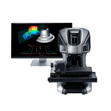
- Benchtop optical systems: measure Ra, Rz, or 3D roughness parameters like Sa. Ideal for parts that are soft, small, easy to scratch, or when you need to measure an entire surface rather than a singular 2D line.
- KEYENCE offers non-contact options for this step: the VK-X4000 series 3D Optical Profiling Microscope and the VR-6000 series Wide-Area Optical Profiler. For help choosing between 2D and 3D approaches, see moving from 2D to 3D roughness measurement.
Frequently Asked Questions
Q What do surface finish symbols mean on a drawing?
A
They state the surface texture requirement for a surface. The basic symbol allows any process; a symbol with a horizontal bar requires material removal by machining, and a symbol with a circle prohibits material removal. Parameter, limit value, and lay are written alongside.
Q What is the difference between an N-grade and Ra?
A
An N-grade is a label, such as N8, that stands for one fixed Ra value, in this case 3.2 µm (125 µin). Ra is the underlying measured parameter. Both describe roughness, so the grade is just a shorthand for the number.
Q What is a standard surface finish for machined parts?
A
There is no single standard, but 3.2 µm (125 µin) Ra is a common default for general machined surfaces. Sealing and bearing surfaces are often held to 0.8 µm (32 µin) or finer. Always follow the value on the drawing.
Q What does RMS mean in surface finish?
A
RMS is root mean square roughness, now called Rq. On a sinusoidal profile it is about 1.11 times Ra. Many older US drawings use "RMS" loosely, so confirm the intended parameter when the tolerance is tight.
Q How do I convert surface finish from µm to µin?
A
Multiply µm by 39.37. For example, 1.6 µm is 63 µin, and 0.8 µm is 31.5 µin though often conventionally rounded to 32 µin.
Q What does the circle inside a surface finish symbol mean?
A
It means material removal is prohibited. The surface must stay as produced, such as cast, forged, or rolled, and any texture requirement applies to that as-produced surface.
Q How is a surface finish callout verified?
A
By measuring the same parameter as the drawing names, using the specified cutoff, and tracing in the right direction relative to the lay. Stylus instruments cover standard Ra checks, and optical systems add areal values such as Sa in addition to standard line roughness measurements.