
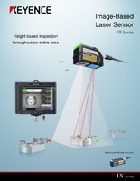
Image-Based Laser Sensor
IX series
Sensor Head 150 mm IX-150
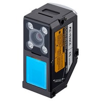
*Please note that accessories depicted in the image are for illustrative purposes only and may not be included with the product.
Specifications
Model | IX-150 | |||
Reference distance | 150 mm 5.91" | |||
Measuring distance | 100 to 200 mm 3.94" to 7.87" | |||
Detection area | Scan mode | Measuring distance of 100 mm 3.94": 56.5 × 42.0 mm 2.22" × 1.65" | ||
Line mode | Measuring distance of 100 mm 3.94": 56.5 mm 2.22" | |||
Laser Light source | Light source | 660 nm (visible light) wavelength red semiconductor laser | ||
Laser class | Class II laser product (FDA [CDRH] Part 1040.10), Class 2 laser product (IEC 60825-1: 2014) | |||
Output | 0.95 mW (FDA [CDRH] Part 1040.10), 1.6 mW (IEC 60825-1: 2014) | |||
Height(Z direction) | Minimum detectable object size | Scan mode | Height | ø1.7 mm ø0.0669" *2 |
Average height | ø0.9 mm ø0.0354" *3 | |||
Pin height | ø0.8 mm ø0.0315" *4 | |||
Line mode | 1.1 mm × 1.1 mm 0.0433" × 0.0433" *5 | |||
Repeatability | 50 μm *6 | |||
Width(X direction) | Minimum edge detection | Line mode | 0.5 mm 0.0197" *7 | |
Estimated detection | (When measuring the height between two points, the minimum step difference is as follows. | |||
Sampling cycle | Scan mode | 120 ms (min.) (typical) | ||
Line mode | 6 ms / 11 ms (selectable) | |||
Image receiving element | Monochrome CMOS image sensor | |||
Image capture lighting | Light source | Red LED | ||
Lighting method | Pulse lighting | |||
Temperature characteristics | 0.04% of F.S./°C *8 | |||
Environmental resistance | Enclosure rating | IP67 | ||
Ambient light | Incandescent lamp, 5000 lux or less *9 | |||
Ambient temperature | 0 to +45°C 32 to 113°F (No freezing) *10 | |||
Relative humidity | 35 to 85% RH (No condensation) | |||
Vibration resistance | 10 to 55 Hz; double amplitude 1.5 mm 0.06"; 2 hours in each of the X, Y, and Z directions | |||
Shock resistance | 500 m/s2 1640'/s2, 3 times in each of the 3 directions | |||
Material | Main unit case: Zinc die-casting / Front cover: Glass, acrylic (hard coat) / Operation indicator cover: TPU / Connector ring: PBT / Connector: Zinc die-casting | |||
Weight | Approx. 190 g | |||
*1 X: Long-side direction of laser, Y: Short-side direction of laser | ||||
![NR-X Data Logger / Data Acquisition Direct connection to other KEYENCE products [Click Here to Learn More!]](/Images/nr-x_series_300_300_01_2089589.jpg)