Vision Systems
- Vision System with Built-in AI VS series
- Intuitive Vision System CV-X series
- Customizable Vision System XG-X series
- GigE camera and lighting for PC-based machine vision VJ series
- Inline 3D Inspection 3D Vision series
- 3D Vision-Guided Robotics 3D VGR series
- Line Scan Technology Line Scan series
- 2D Vision-Guided Robotics 2D VGR series
- LED Lighting CA-D series
- Lenses (for Machine Vision) CA-L series
- Machine Vision System Database VisionDatabase series
- Aerospace
- Automation Equipment/Machine Building
- Automotive
- Commodities
- Defense
- Electric Vehicles
- Electronic Device
- Fabric/Textile
- Food/Beverage Packaging
- Logistics
- Machine Tools
- Marine
- Medical Device Manufacturing
- Mining/Metals
- Paper Manufacturing
- Pharmaceuticals
- Printing
- Semiconductor/Manufacturing Electronics
- Solar
- Tobacco
- Vision-Guided Robotics
How to Choose the Right Industrial Machine Vision Camera for Your Application
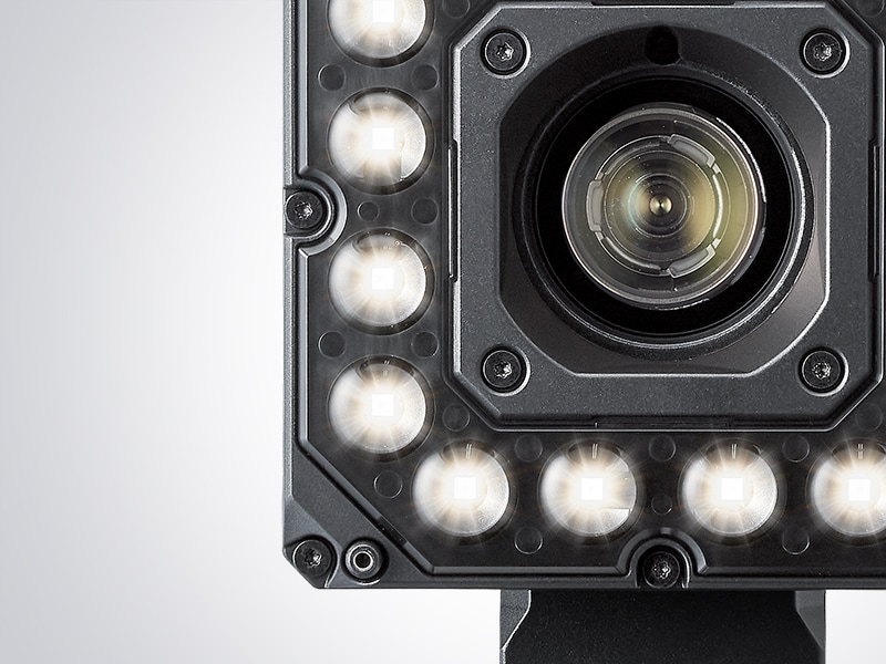
The camera you choose becomes the foundation for your machine vision system, and picking the right camera is more than just a technical decision; it dictates what data can be observed and how stable the results will be over time. In high-speed production lines and tight tolerances, the camera has to deliver more than an image; it has to deliver confidence.
Key Factors to Consider When Choosing an Industrial Camera
Resolution
Resolution is the smallest feature a machine vision system can detect, and for reliable pass/fail judgments, this feature should cover at least a 3×3 pixel grid.
Frame Rate
Fast production lines need cameras with high frame rates to capture clear images without blur and allow enough processing time for accurate analysis.
Lighting Conditions
Proper lighting is essential to accurately capture object edges and surface flaws, and the ideal setup depends on the material, shape, and inspection needs.
Field of View
The field of view (FOV) defines the camera’s capture area, influenced by sensor size, lens focal length, and working distance.
Types of Industrial Vision Cameras and Their Applications
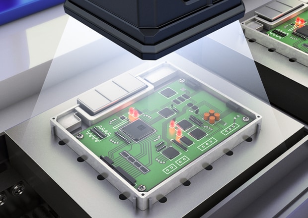
Area Cameras
These cameras are flexible and easy to set up, with the capability to capture 2D images in a single exposure. They use a rectangular sensor array to perform part presence inspections, dimension verification, or label readings.
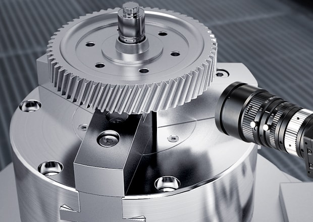
Line Scan Cameras
Line scan cameras capture one row of pixels at a time and assemble the image as the target moves past the sensor. High-speed line cameras can capture fine surface detail across long sections of material without sacrificing accuracy.
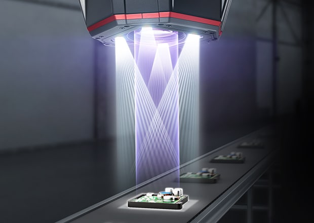
3D Vision Cameras
These cameras are well-suited for applications that require height measurements or geometric surface profiling. They provide depth data in addition to standard 2D images, using technologies like structured light, stereo imaging, or time-of-flight. 3D vision cameras like the XT by KEYENCE are designed so that no external lighting is needed.
Camera Connectivity and Integration
Camera Power and Integration
Industrial vision cameras typically run on 24V DC or Power over Ethernet (PoE). PoE simplifies setup by delivering power and data over a single cable, which is ideal for tight spaces or multi-camera systems. For traditional setups, 24V is standard across industrial environments.
Integration depends on the system architecture, with cameras connecting directly to PLCs or through interfaces like GigE or USB3 for PC-based processing. The decision is based on factors such as data volume, speed, and the number of cameras involved.
Software Compatibility
Many machine vision systems are designed to reduce setup complexity and support direct integration with PLCs and robot controllers. The KEYENCE VS Series offers an intuitive, icon-based interface that supports rules-based or AI-powered inspections. No middleware is required, and software compatibility is maintained across product lines.
How to Optimize Camera Selection for Your Specific Industry Needs
Industry-specific requirements often dictate camera selection more precisely than general performance metrics.
- In automotive, cameras are expected to inspect moving parts at high speed, verify assembly accuracy, and capture small defects in metal and plastic components.
- Electronics systems must handle micro-scale measurements, inspect reflective surfaces, and verify precise pin alignments or solder joints.
- In medical device and pharmaceutical manufacturing, machine vision systems must confirm label accuracy, lot code readability, and detect contamination, often on transparent or glossy surfaces.
Major Items to Be Checked Before Introducing Machine Vision
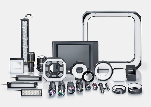
Machine vision applications can be roughly divided into four categories—quantity/count inspections, foreign matter/defect inspections, dimension inspections, and position inspections—with each type used in a variety of industries. This section introduces various tips for selecting a camera that appropriately suits the purpose.
Step 1. Selecting the Devices Required for Inspection
Choose the correct devices that meet the inspection requirements.
- Camera
- Controller
- Lighting
- Lens
- Monitor
Step 2. Sensing and Judgment
Perform testing on the actual target with the machine vision system.
- Reference parts for OK and NG products
- Inspection cycle time
- Variety of inspection items
Step 3. Selecting the Installation Location and Procedure
Review the specific installation locations.
- Target in motion/stationary
- Environmental conditions, including ambient light and vibration
Step 4. Controls for Automation
Review the I/O controls for the machine vision system.
- Image capture timing
- Judgment output
- PLC control
- Data output
Step 5. On-Site Testing
Test the machine vision system on the actual production line.
- Fine setup adjustment
- Statistics
- I/O control check
Step 6. Understanding Basic Operations
Basic setup procedures to maintain stable inspection.
- Setting tolerances
- Sensitivity adjustment
- Changing the inspection settings
- Item registration
Each type has a color and monochrome version available.
Machine vision applications can be roughly divided into four categories—quantity/count inspections, foreign matter/defect inspections, dimension inspections, and position inspections—with each type used in a variety of industries. This section introduces various tips for selecting a camera that appropriately suits the purpose.
- High-resolution type
- High-speed type
- Standard type
- Compact type
We’re here to provide you with more details.
Reach out today!

Selecting Instruments Required for Inspection Camera Selection
Step 1: Selecting Based on Resolution (High or Standard Resolution).
The image sensor (CCD or CMOS) used in a vision camera is an aggregate of small pixels arranged in a grid. Standard type image sensors commonly have 310000 pixels (640 × 480) while high-resolution types can have anywhere from 2 to 21 megapixels. The application requirements will dictate the type of camera that is suitable.
As a general rule, select a camera based on the size of the field of view and the pixel resolution. The size of the field of view is the area captured on an inspection target, which can be changed by the lens used. The pixel resolution means how many millimeters each pixel is equal to, and the relationship is expressed by the following equation.
Pixel resolution = Size of field of view in the Y direction (mm) ÷ sensor pixel count in the Y direction
For an example of pixel resolution, a 30 mm 1.18″ field of view in the Y direction will be used. The image sensor types that will be used in this example are the 310000-pixel standard model (Y = 480 pixels) and the general-purpose 2-megapixel high-resolution model (Y = 1200 pixels).
[Pixel resolution of a 310000-pixel camera] = 30 mm 1.18″ / 480 pixels = 0.063 mm 0.002″/pixel
[Pixel resolution of a 2-megapixel camera] = 30 mm 1.18″ / 1200 pixels = 0.025 mm 0.001″/pixel
If the desired pixel resolution is known for the application, the same equation can be used to calculate the approximate field of view the camera will provide.
Appearance inspection and dimension inspection are typical applications for machine vision. When performing pass/fail judgment, detection capability is considered for appearance inspections, and dimensional tolerance is considered for dimensional inspections.
The following general principles can be applied as a reference for calculation:
Detection capability = 4 pixel area
Dimensional tolerance = ±5 pixels
Using the pixel resolution calculated above, the detection capability for appearance inspection can be obtained.
[Detection capability of a 310000-pixel camera] = 0.063 mm 0.002″/pixel × 4 pixel area = 0.25 mm 0.01″ area
[Detection capability of a 2-megapixel camera] = 0.025 mm 0.001″/pixel × 4 pixel area = 0.1 mm 0.004″ area
Based on these calculations, if the inspection requires detection of foreign particles that are as small as 0.1 mm 0.004″ with a field of view of 30 mm 1.18″, a camera with a resolution of 2MP or more is needed.
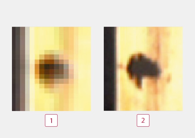
Reference: Enlarged view of 0.5 mm 0.02″ foreign particle in a 30 mm 1.18″ field of view
-
1310000 pixels
-
22 megapixels
* 2 megapixel cameras can capture images that show fine changes in higher contrast.
You can select a camera with the optimal number of pixels by considering pixel resolution as the criteria for pass/fail judgment.
Step 2: Selecting Based on Color or Monochrome Type Image Sensor
One common question when selecting a camera type is whether to use a color or monochrome type. Generally speaking, if the differences at the sensing points are detected based on hue, the color cameras may have an advantage. The following shows an example of using color processing to detect a yellow stain on a white base, which is not easily detectable by a monochrome camera.

In cases like this, when there is little difference in brightness, the contrast difference with the background is so slight that a monochrome camera is less likely to provide correct detection. Picture (2) shows that internally, the contrast between yellow and white is clearly detected with the color camera. Picture (3) shows a contrast image obtained by using the stain inspection tool. This shows that stable detection is available for actual inspections using color processing.
-
1Image captured by a color camera
-
2Color-processed image
-
3Stain inspection contrast image
-
4Image captured by a monochrome camera
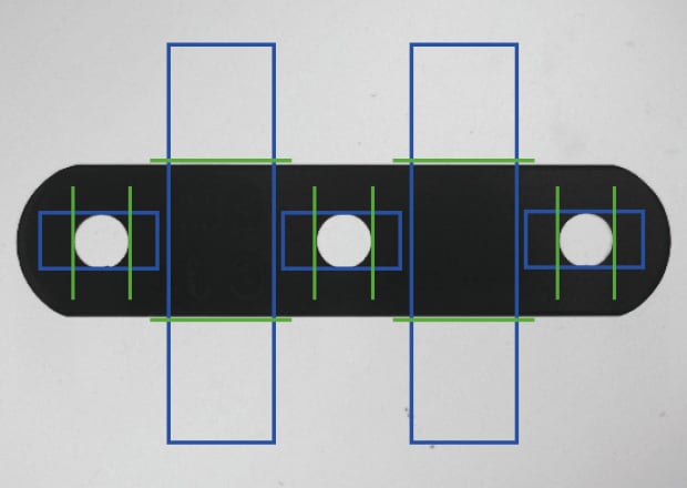
Dimension inspection of metal workpieces using backlight
However, monochrome cameras do have some advantages over color. For dimension measurement using a backlight, as shown left, monochrome cameras are ideal as there is a large contrast change. Furthermore, since color cameras use a Bayer filter (where each pixel is dependent on the neighboring pixels to get the full color information), they are generally less accurate than monochrome cameras for dimensional type measurements using edges.
Determine whether the sensing points have a hue variation or a brightness variation when selecting the image sensor!
Step 3: Selecting Based on Image Transfer Speed (High-Speed or Standard Models)
Cameras used in machine vision can have different image transfer speeds even when the pixel counts are the same. Using a 310000-pixel type as an example, standard models offer a transmission time of 16.0 ms while high-speed models can achieve a transmission time of 1.7 ms. Even higher speeds can be achieved via a partial capture function. High-speed cameras are not only effective for fast production lines, but they are advantageous for normal speed applications, as there is more processing time available for image filtering and tools that can stabilize the inspection.
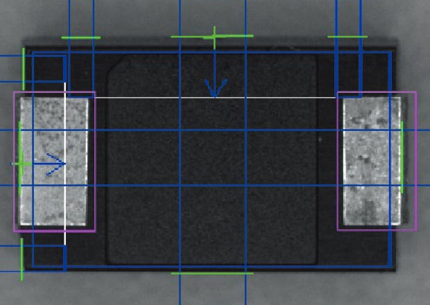
Appearance inspection of chips (7× speed + 310000 pixel monochrome camera)
Trigger interval 3 ms / Inspection capability 19980 items per minute
- Stain inspection of the molded parts
- Dimension inspection
- Position correction (XYθ)
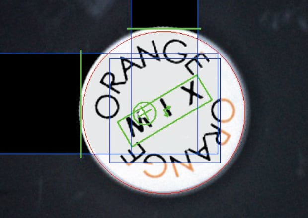
Appearance inspection of caps (7× speed + 310000 pixel full color camera)
Trigger interval 12 ms / Inspection capability 4999 items per minute
- Print quality inspection
- Position correction (XY)
- Angle correction (360 degrees)
Benefits of selecting a high-speed camera include stable processing in addition to faster inspection cycle time!
Step 4: Selecting Based on Camera Size (Compact or Standard Models)
Compact cameras are reduced in size, but are equipped with the same specifications as larger-sized cameras. Standard and high-resolution (2MP) compact types are available in color or monochrome. Compact types are primarily selected to efficiently use limited installation space. Particularly in cases where machine vision is to be installed in the available space of an existing facility, it is beneficial to use compact cameras to fit in a limited area without changing the machinery.
As shown below, the installation space needed for a camera is the sum of A (WD: working distance, which is the distance between the tip of the lens and the workpiece), B (lens size), C (camera size), and D (cable space, including bends).
Example: Using a standard camera with lens with a focal distance of 6 mm 0.24″ and a field of view of 30 mm 1.18″
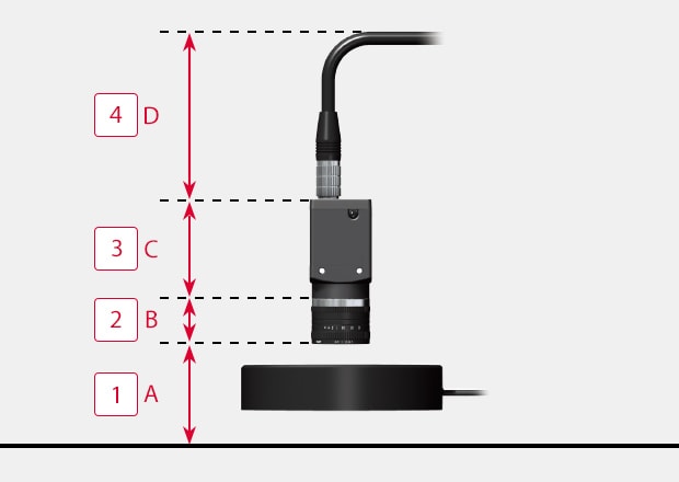
A space of 215 mm 8.46″ in the upward direction is required for this installation.
A + B + C + D = 215 mm 8.46″
-
140 mm 1.57″
-
240 mm 1.57″
-
350 mm 1.97″
-
485 mm 3.35″
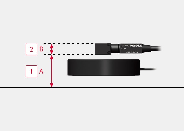
A significant space-saving can be achieved by using a combination of a compact camera and a side view attachment in cases where a space of 215 mm 8.46″ cannot be provided.
Installation space is only 45 mm 1.77″ (A + B).
-
130 mm 1.18″
-
215 mm 0.59″
Selecting compact cameras based on the known required installation space can prevent unnecessary changes to the production machine.
Selecting the Devices Required for Inspection: Camera (Summary)
The camera type is a key element to be selected for image processing to ensure stable inspection. The below quick reference chart provides a summary of the different camera types that are available.
[Step 1] Select by appearance: how many pixels will satisfy the required accuracy?
[Step 2] Select by transmission speed: select high-speed type when you need high-speed or more stable processing.
[Step 3] Select by camera size: select a compact type when installation space is limited.
[Step 4] Select by CCD type (color/monochrome): select a color camera when you want to recognize changes in hue.
| [1] | 21 million pixels | 5 million pixels | |||
|---|---|---|---|---|---|
| 5104 × 4092 | 2432 × 2040 | 2432 × 2050 | |||
| [2] | 109.9 ms | 27.6 ms*1 50.3 ms*2 |
29.0 ms*1 52.4 ms*2 |
61.2 ms | |
| [3] | Standard | Standard | Standard | ||
| [4] | Monochrome | CA-H2100M | CA-HX500M | - | CV-H500M |
| Color | CA-H2100C | - | CA-HX500C | CV-H500C | |
Scroll
| [1] | 2 million pixels | |||||
|---|---|---|---|---|---|---|
| 1600 × 1200 | ||||||
| [2] | 11.6 ms*1 20.1 ms*2 |
11.6 ms*1 20.2 ms*2 |
29.2 ms | 58.5 ms | ||
| [3] | Standard | Standard | Standard | Standard/Compact * | ||
| [4] | Monochrome | CA-HX200M | - | CV-H200M | CV-200M | CV-S200M |
| Color | - | CA-HX200C | CV-H200C | CV-200C | CV-S200C | |
Scroll
| [1] | 310000 pixels to 470000 pixels | |||||||
|---|---|---|---|---|---|---|---|---|
| 784 × 596 | 512 × 480 | 784 × 596 | 512 × 480 | 640 × 480 | ||||
| [2] | 2.9 ms*1 5.2 ms*2 |
1.7 ms*1 2.8 ms*2 |
2.9 ms*1 5.3 ms*2 |
1.7 ms*1 2.9 ms*2 |
4.7 ms | 16.0 ms | ||
| [3] | Standard | Standard | Standard | Standard | Standard/Compact * | |||
| [4] | Monochrome | CA-HX048M | - | CV-H035M | CV-035M | CV-S035M | ||
| Color | - | CA-HX048C | CV-H035C | CV-035C | CV-S035C | |||
Scroll
* 1 during use CV-X400 Series and CV-X200 Series + CA-EC80HX / EC80L
* 2 When using CV-X100 Series or CV-X200 Series + CA-EC80
KEYENCE Camera Options
KEYENCE offers a full range of machine vision systems, each engineered for specific inspection needs:
- VS Series: A smart camera platform with built-in AI and optical zoom for rapid deployment in dynamic inspection environments.
- CV-X Series: High-resolution system (up to 64MP) with intuitive configuration tools and support for both AI and rule-based inspections.
- XG-X Series: A modular platform for custom programming and multi-camera applications, including support for 2D and 3D sensors.
Contact KEYENCE for Expert Assistance in Choosing the Right Camera
KEYENCE offers direct technical support, on-site testing, and application-specific guidance.
Contact a product expert to configure a system tailored to inspection goals and production constraints.
Contact us to learn more about how our advanced technology can help take your business to the next level.
Contact Us
Industrial Vision Camera FAQs
What is an Industrial Machine Vision Camera?
An industrial machine vision camera is designed to “see” and understand images like humans do. However, unlike typical machine vision cameras used for small businesses and shops, cameras for industrial applications are more robust and can withstand harsh environmental conditions.
Additionally, industrial machine vision cameras can capture a higher number of images per second and send that data directly to the machine vision system for processing. These types of cameras comprise two scanning technologies: line scan (1D) and area scan (2D) cameras. The difference lies in how these capture images, making them suitable for different applications.
KEYENCE’s vision systems, like the CV-X Series, are equipped with high-resolution area scan cameras capable of capturing detailed images at high speeds. These cameras are designed specifically for industrial use and can easily handle the demands of factories, ensuring quality and improved efficiency.
How Does an Industrial Vision Camera Differ From a Standard Camera?
Industrial machine vision cameras differ significantly from typical network cameras. Network cameras are mostly used in residential and commercial settings for surveillance and security purposes. As such, they’re often capturing compressed images, which reduces the amount of data the system has to process and store, often impacting image quality.
Industrial machine vision cameras work on a fundamentally different principle compared to standard cameras. They often rely on laser scanners, 3D-image capturing, blackbody radiation, and multispectral technologies for capturing images, and they’re capable of capturing images at extreme framerates.
KEYENCE’s industrial and customizable vision systems, like the XG-X Series, allow for flexibility and control in image capturing, analysis, and processing.
What Factors Should Be Considered When Selecting a Machine Vision Industrial Camera?
The factors for selecting an industrial machine vision camera depend on your application. If your machine vision system measures component dimensions and alignment, you should consider all the factors associated with laser scanners. However, if your manufacturing process requires precise temperature measurements, you should opt for an infrared camera.
Generally, factors you want to consider are resolution, type of image sensor, image transfer speed, and camera size. More specific factors depend on the specific needs of your particular application. e.g., quality control machine vision cameras in electronics require higher precision than those used in simple presence/absence checks.
KEYENCE’s range of machine vision cameras offers a variety of resolutions, image sensors, and transfer speeds to meet different demands. From the VS Series to the RB Series, each system and/or camera is designed to provide high-speed, high-resolution imaging for various industrial applications. They come in compact sizes, making them easy to integrate into existing production lines without taking up too much space.
How Can I Determine the Appropriate Resolution for an Industrial Vision Camera?
Your application requirements dictate the appropriate resolution. As a basic rule, you should choose a camera based on the size of the field of view and pixel resolution. The FOV size is based on the area you want to capture for inspection, and it can be manipulated by using different lenses.
Pixel resolution refers to the ratio between the screen size and pixel count per dimensional axis, and it’s very application-dependent. Precise measurement applications require higher pixel resolution compared to presence-check applications, and this factor is usually calculated per application.
How Can a Machine Vision Industrial Camera Be Used for Multiple Applications Within Industries?
Thanks to their high adaptability and compatibility with various software and hardware systems, machine vision cameras have plenty to offer in terms of versatility and use across multiple applications.
For example, the same camera used for inspecting part surfaces or checking for missing components can also be used for robotic guidance in the automotive industry. Likewise, thermal imaging cameras used in industrial baking can also be used in electronics diagnostics when checking for shorts and faults that produce excessive heat.
A prime example of this is the VS Series, which can handle a considerable range of inspections and also has an industry-first zoom function called ZoomTrax. The camera's ease of use and simple setup make it a valuable asset.
What Is the Difference Between an Area Scan Camera and a Line Scan Camera?
Area scan cameras capture full 2D images in one exposure and work best for static or discrete inspections. Line scan cameras build images line-by-line as objects move past, making them ideal for continuous or high-speed applications.
How Can I Determine the Appropriate Resolution for an Industrial Vision Camera?
Divide the field of view by the smallest feature to detect. For example, detecting a 0.01 mm flaw across 30 mm requires at least 3,000 pixels in that axis.
How Do I Know if My Existing Camera Setup Is Sufficient for My Current Application?
Watch for false rejects, missed defects, or slow performance. These may indicate mismatches in resolution, lighting, or frame rate.
How Often Should I Calibrate My Machine Vision Camera?
Calibration is recommended at setup, after hardware changes, and during scheduled maintenance.
We’re here to provide you with more details.
Reach out today!

Related Downloads
Related Products
Industries
- Aerospace
- Automation Equipment/Machine Building
- Automotive
- Commodities
- Defense
- Electric Vehicles
- Electronic Device
- Fabric/Textile
- Food/Beverage Packaging
- Logistics
- Machine Tools
- Marine
- Medical Device Manufacturing
- Mining/Metals
- Paper Manufacturing
- Pharmaceuticals
- Printing
- Semiconductor/Manufacturing Electronics
- Solar
- Tobacco
- Vision-Guided Robotics

