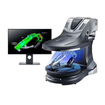
3D Scanner
Easy Method for Measuring Gear Diameter Over Pins
-
Tags:
- Metals , Cutting , Mechanical elements
Key Takeaways
- Perform non-contact diameter over pins measurements by capturing a full 3D scan with the VL Series.
- Single‑shot scans (~8 s) capture full gear geometry; no fixtures or positioning needed.
- Create virtual pin placements/cross‑sections to calculate diameter‑over‑pins and tooth thickness.
- Captures complex gear types (spur, helical, internal, bevel, rack) with high accuracy, regardless of the operator.
- Fast CAD overlay and quantitative pass/fail comparison simplifies inspection and reduces rework.
Gears are fundamental machine elements used to transmit power. Their meshing teeth transfer rotational motion, and by pairing gears of different sizes, engineers can precisely control the speed ratio between driving and driven shafts. Found everywhere from bicycles and wristwatches, to turbines and industrial machine tools, gears are integral to nearly every mechanical system we rely on.
Effective gear design demands a careful balance of priorities: high dimensional accuracy for smooth operation, robust durability for sustained power transmission, and a constant strive toward miniaturization and weight reduction. Adding further complexity, gears inevitably wear and deform over time, meaning these effects must be accounted for from the earliest stages of design.
Among the many factors that determine a gear's performance, tooth thickness is one of the most critical. It is most commonly evaluated using the measurement over pins method, a reliable technique for verifying that a gear has been manufactured to specification. In this article, we introduce key gear terminology and types, walk through the measurement over pins technique and its inherent challenges, and demonstrate how KEYENCE's VL Series 3D Scanner CMM provides an effective solution.
Types of Gears
Spur Gear
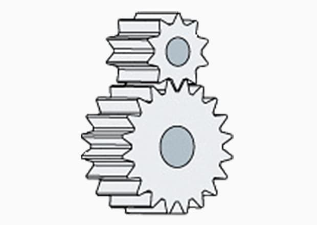
This is the most common type of gear, with teeth cut parallel to the axis of rotation. It is characterized by its simplicity and ease of manufacturing. It is also known as a straight-cut gear.
Helical Gear
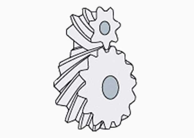
A helical gear is a gear where the teeth are twisted in a helical path. Compared to spur gears, more teeth are in mesh at once, resulting in higher strength and less vibration and noise.
Double Helical Gear
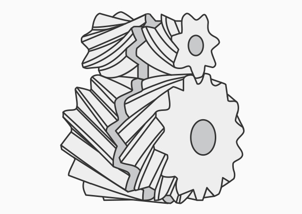
A double helical gear has a shape like two helical gears placed side-by-side. By combining gears with opposite tooth inclinations, it can cancel out the thrust load generated by helical gears. When placed directly next to one another, they are known as a herringbone gear.
Internal Gear
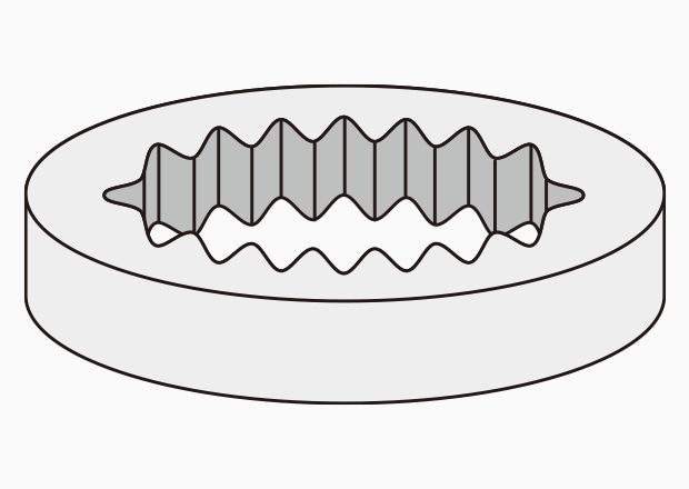
This is a type of spur gear with teeth on the inside. A major difference is that while two meshing external spur gears rotate in opposite directions, two meshing internal gears rotate in the same direction.
Rack and Pinion
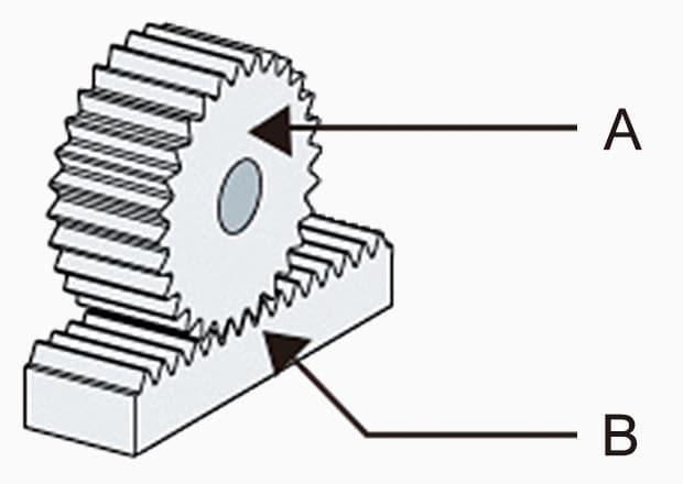
A rack is a plate- or rod-shaped gear (part B), and a pinion is a small cylindrical gear (part A). The combination of these is called a "rack and pinion." It can convert rotational motion into linear motion and is used in applications like automotive steering systems, conveyors, and machine tools.
Straight Bevel Gear
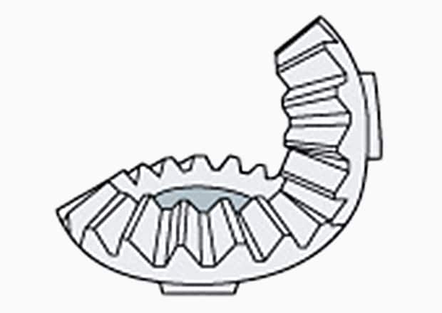
A bevel gear is a frustoconical gear, named for its umbrella-like shape. Among them, a bevel gear with straight teeth is called a "straight bevel gear." It is a type of intersecting-axis gear used to change the direction of rotational motion.
Spiral Bevel Gear
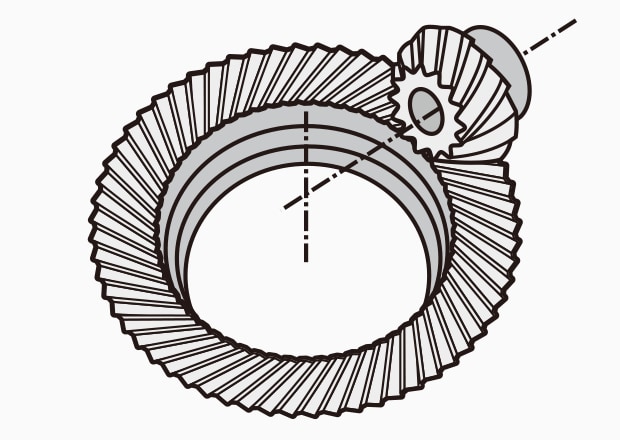
A gear with teeth arranged in a spiral on a frustoconical base is called a "spiral bevel gear." It is a type of intersecting-axis gear that changes the direction of rotational motion.
Helical Bevel Gear
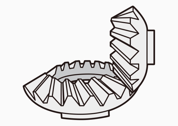
This is a type of bevel gear that's similar to a spiral bevel gear; however, while spiral bevel gears have curved teeth, helical bevel gears have straight teeth, resulting in differences in contact ratio, etc.
Worm Gear
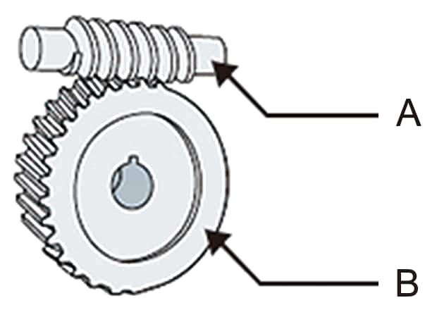
A worm gear consists of a threaded shaft called a "worm" (part A) and a corresponding "worm wheel" (part B). Worm gears are classified as skew-axis gears, often with a 90° intersection angle. They have a large reduction ratio and are used when a large speed reduction is needed while changing the direction of rotation.
Hypoid Gear
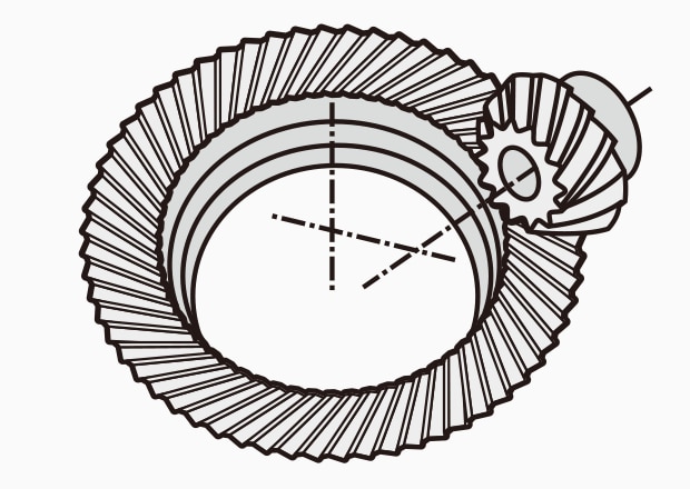
This is a type of spiral bevel gear, but with the major difference that the axes of the driving and driven gears do not intersect, making it a "skew-axis gear." It is typically used in high-torque applications such as automotive drivetrains and reducers for machine tools and robots.
Terminology of Gear Parts
Using a spur gear as an example, we will now introduce the names of the various parts of a gear.
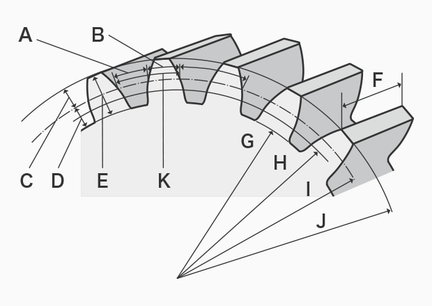
[A] Tooth Space Width
[B] Tooth Thickness
[C] Addendum
[D] Dedendum
[E] Whole Depth
[F] Face Width
[G] Root Diameter
[H] Base Circle Diameter
[I] Pitch Circle Diameter
[J] Tip Diameter (Outside Diameter)
[K] Circular Pitch
Methods for Measuring Tooth Thickness
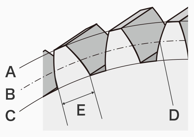
A: Addendum circle
B: Pitch circle
C: Dedendum (root) circle
D: Pitch point
E: Tooth thickness
Tooth thickness refers to the thickness of a single tooth on the pitch circle. The illustration shows the tooth thickness of a spur gear. Measurement methods for tooth thickness include the "chordal tooth thickness method", the "span measurement method", and the "measurement over pins (or balls) method".
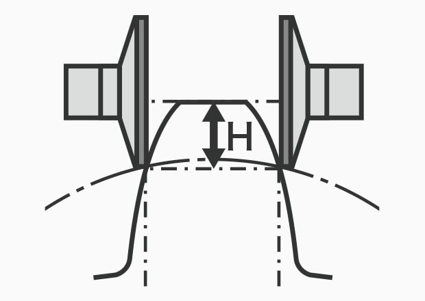
Chordal Tooth Thickness Method
Chordal tooth thickness refers to the length of the chord between two symmetric points on the flank surfaces on the pitch circle. In the chordal tooth thickness method, the thickness at the tooth height (H) is measured with a tooth-thickness caliper, a tooth-thickness micrometer, or a gear-profile caliper.
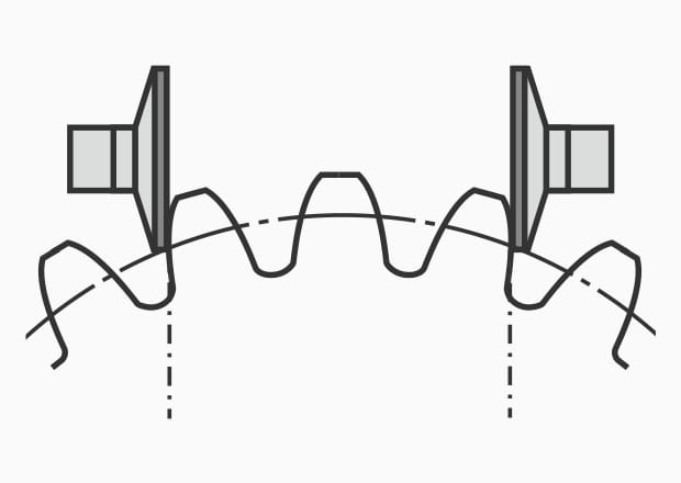
Span Measurement Method
The length of a certain number of teeth is measured with a tooth-thickness micrometer or similar instrument. The number of teeth clamped at this time is called the "span tooth count," and because the tooth thickness is measured from that tooth count, the method is called the "Span Measurement Method." Because it is measured from the tooth count, setting a reference surface is unnecessary.
Measurement Over Pins (or Balls) Method
The measurement over pins (or balls) method is a way to measure tooth thickness by placing pins or balls in the tooth spaces and measuring the external dimension over the pins for external gears, or the internal dimension for internal gears. Because it uses pins or balls, it is called the "measurement over pins method," "measurement over balls method," or "ball method." The dimension obtained by this method is called the "measurement over pins" or "diameter over pins" for external gears, and "measurement between pins" for internal gears.
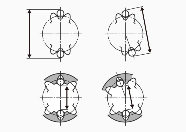
For gears with an even number of teeth, pins or balls are placed in opposing tooth spaces; for an odd number of teeth, they are placed in tooth spaces offset by 180 °.
Regarding the diameter of the pins or balls used, for a standard gear, it is ideal that they contact on the reference pitch circle diameter, and for a shifted (displaced) gear it is ideal that they contact at the diameter of '{reference pitch circle diameter + (module × profile shift coefficient × 2)}'. However, since the pin or ball diameters calculated by the formula often result in nonstandard values, it is common to use the closest commercially available pin or ball instead.
For spur and helical gears, tooth thickness is measured using two pins or balls together with a micrometer or similar instrument. For internal gears, two pins or balls are used with a block gauge or equivalent.
Challenges of Tooth Thickness Measurement with the Measurement Over Pins Method
The over-pin method generally measures tooth thickness using calipers, gear micrometers, or coordinate measuring machines (CMMs). However, each of these measurement methods has its own challenges. Here, we will explain the issues associated with conventional tooth thickness measurement.
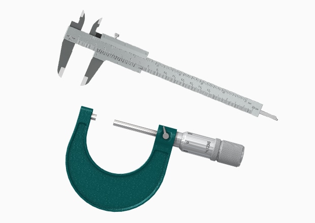
Calipers and Gear Tooth Micrometers
The most common instruments are calipers or dedicated gear micrometers. Measuring the over pin diameter by hand involves placing the tool’s tips on the part and reading the value, which makes the result prone to operator variability and error.
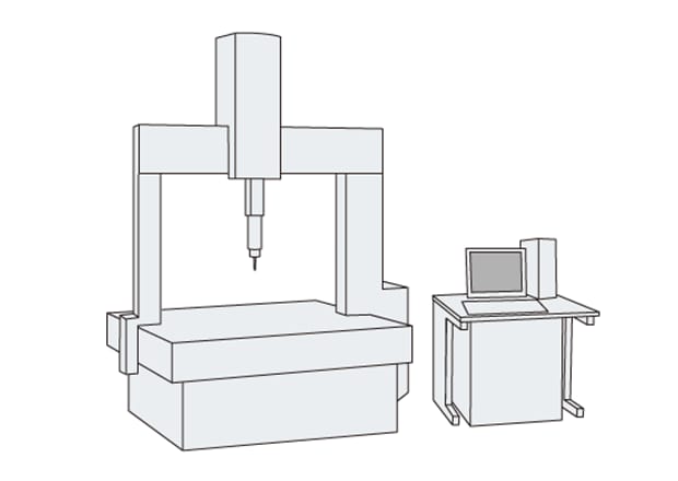
Coordinate Measuring Machine (CMM)
A coordinate measuring machine (CMM) works by using a contact probe to collect three-dimensional coordinates from a workpiece secured on its stage. These coordinates capture the lateral, longitudinal, and vertical positions of points across the part's surface, allowing the CMM to measure dimensions, positional relationships, contours, and geometric tolerances with impressive precision.
However, when it comes to complex features such as gear tooth thickness, the CMM's contact-based approach begins to show its limitations. Because data is gathered one point at a time, measuring intricate geometries requires a large number of individual probe contacts, making the process time-consuming. Compounding this challenge, programming a CMM to handle complex shapes like gears demands a high level of operator expertise, raising both the skill barrier and the potential for human error.
Issues with calipers, gear micrometers, and coordinate measuring machines (CMMs)
Measurement of tooth thickness with hand tools (e.g., calipers or gear micrometers) is simple and cost‑effective, but prone to operator error and can be time‑consuming. In contrast, coordinate measuring machines (CMMs) deliver much higher accuracy, yet require part fixturing and leveling and require skilled operators. Achieving the highest precision with a CMM also typically requires increasing the number of measurement points, which increases inspection time.
An Easier Way to Measure Diameter Over Pins
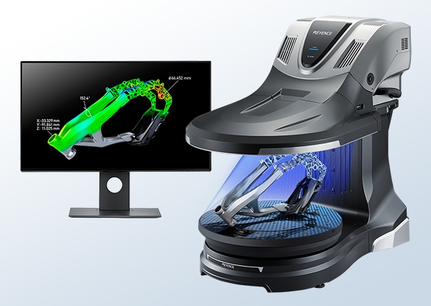
Conventional measurement methods has many challenges. KEYENCE's VL Series 3D Scanner CMM solves these challenges and enables effortless measurement of the diameter over pins.
The VL Series can capture the entire 3D shape of an object using a non-contact method. It can scan an object in as fast as eight seconds, and eliminates operator-induced variability and errors. Here we will introduce the advantages of measuring gear over‑pin diameter using the VL Series 3D Scanner CMM.
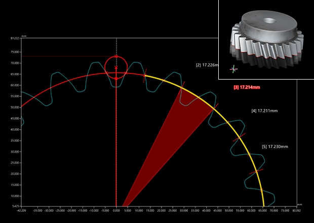
Benefit 1: Capture the Entire Surface of the Gear
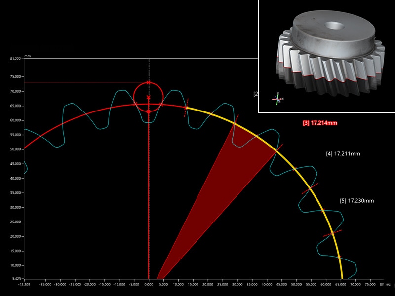
KEYENCE'S VL Series 3D Scanner CMM captures an entire 3D scan of a gear, and by using cross-sectional views cut from the data, any user can easily measure the over-pin diameter. The entire geometry can be captured with a single click, dramatically reducing the time needed for measuring tooth thickness. Because the system captures the object as a continuous surface rather than as discrete points or lines, it can accurately measure complex shapes such as gears.
The VL Series 3D Scanner CMM eliminates the variability of calipers or micrometers, and does not require the experience for a CMM, all while delivering accurate, repeatable tooth thickness measurements regardless of who performs them.
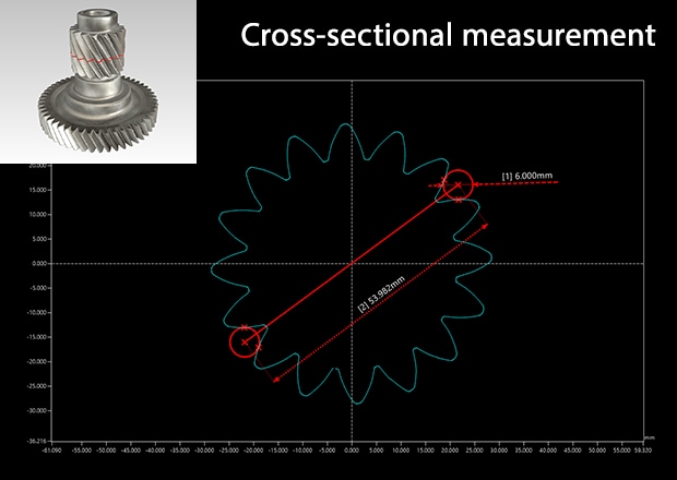
Benefit 2: Measure Complex Gear Shapes Easily
Any gear (spur, helical, internal, etc.) can have its over‑pin diameter easily measured by KEYENCE’s VL Series 3D Scanner CMM. A single one‑shot scan of the entire gear captures the over‑pin diameter.
You can apply the same measurement procedure used on one part to multiple parts at once. This enables fast shape comparisons across multiple items and supports quick tasks such as quantitative pass/fail analysis and automated rejection of defective parts.
Making Gear Diameter Over Pins Measurement Effortless
With KEYENCE's VL Series 3D Scanner CMM, measuring the diameter over pins of gears, which was traditionally difficult, becomes an effortless task.
- No positioning or fixtures required. Simply place the gear on the stage and scan to measure tooth thickness.
- Non-contact scanning is completed in as little as eight seconds, collecting accurate diameter-over-pins data in a short time.
- Capture full 3D scans of complex shapes to easily measure diameter-over-pins.
- Non-contact measurement significantly reduces variations and errors between operators, ensuring stable results.
- Quantitative comparison and analysis of multiple measurement data sets are easy, simplifying pass/fail judgment.
Tooth thickness measurement, which was traditionally very labor-intensive and difficult to perform accurately, can now be done, even for complex gear shapes like spur, helical, double helical, internal, rack and pinion, and straight bevel gears with KEYENCE's VL Series 3D Scanner CMM.