3D Scanner
How to Measure Tube and Pipe Bending
Key Takeaways
- The VL Series 3D Scanner CMM enables non-contact, full 360° scans for fast, accurate pipe bend measurement.
- Single-shot 360° scanning eliminates the need for repositioning, making it easy to measure bend radius and bend angle in one pass.
- Comparing scans directly against 3D CAD data allows you to instantly visualize deformation, wall thinning, and fabrication errors.
- Compatible with a wide range of complex bend types (including draw, press, roll, and stretch) on materials like stainless steel, carbon steel, alloy, aluminum, and copper.
A pipe is any round, hollow tube composed of metal, resin, or other materials that are used as a conduit for moving gas or liquid. A tube is similar to a pipe but is used for support or other applications that don't involve transferring a liquid or gas.
Because of their geometry and material properties, pipes and tubes serve many functions, from transporting liquids and gases to everyday uses like handrails and furniture frames. These are often shaped to match their usage and environment, which makes measuring their geometry both challenging and time-consuming.
In this article we explain how to measure the dimensions of bent pipes. We cover the fundamentals of tube and pipe bending, common processing and measurement methods, the challenges those methods present, and practical solutions. We also introduce KEYENCE’s VL Series 3D Scanner CMM, which can measure bending geometries that were previously difficult to capture with conventional techniques.
What are Pipes, Steel Pipes, and Piping?
A pipe refers to hollow tubing in general. Piping, meanwhile, refers to a structure composed of the tubes (pipes or hoses), fittings, valves, instruments, protective materials, and more that are required for the transportation of liquids or gases.
Types of Metal Pipes
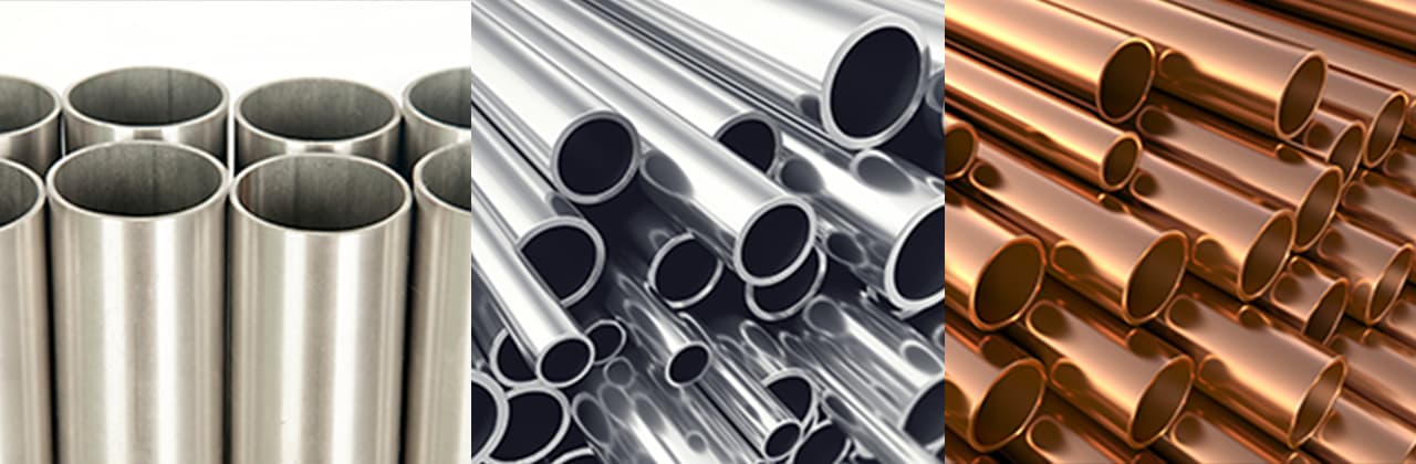
Stainless Steel Pipe
Made from alloy steel containing 10.5% or more chromium, stainless steel pipes are among the most widely used steel pipes available. Their popularity stems from a combination of high durability, corrosion resistance, relatively low cost, and suitability for weight reduction applications.
Carbon Steel Pipe
A pipe primarily made of carbon steel, an alloy of iron and carbon, is called a "carbon steel pipe." In addition, it is classified as low-carbon steel, medium-carbon steel, or high-carbon steel depending on the carbon content.
Alloy Steel Pipe
An alloy steel pipe is a pipe made from carbon steel alloyed with elements such as chromium, nickel, or molybdenum. These pipes are commonly used in piping systems for heat exchangers and heating furnaces.
Aluminum Pipe
An aluminum pipe is a lightweight, corrosion‑resistant tube made from aluminum. Because pure aluminum has relatively low strength, alloys such as duralumin are typically added. Aluminum pipes are mainly used in heat‑exchanger piping and in marine applications.
Copper Pipe
Copper pipes are corrosion‑resistant tubes, with resistance to water and soil. Strength can be increased by alloying copper with elements such as zinc, tin, gold, or silver. Copper’s natural antimicrobial properties make it suitable for refrigerant and air lines in air conditioners as well as potable water supply.
What is Pipe Bending?
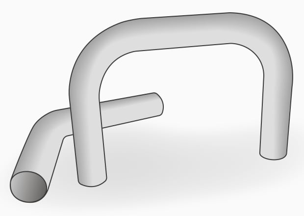
Bending is a metalworking technique. For steel pipes, two principal methods are cold bending and warm bending. Temperature control is critical, since steel’s strength and brittleness depend on temperature.
Cold Bending
The method of bending steel at temperatures from room temperature up to 720°C (1328°F) is called 'cold bending.' Techniques include bender bending and roll bending, and use specialized machines apply pressure to form the material into the desired shape.
Warm Bending
During warm bending, steel is heated to the 800°C (1472°F) – 900°C (1652°F) range. Because warm bending requires less force than cold bending, it allows for larger deformations and tighter radii, making it well suited for small‑radius or sharp‑angle bends.
Flame Bending
Flame bending is a process that bends steel by exploiting thermal expansion and contraction. The area is heated and then rapidly cooled, causing contraction that produces the bend. This method enables high‑precision bending even for large workpieces.
Types of Bending Processes
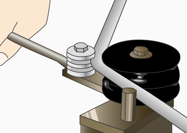
Methods for bending metal pipes mainly include "draw bending" using a pipe bender and "roll bending" which uses three rollers.
Draw Bending
Draw bending is a versatile pipe‑bending method suitable for a wide range of applications. It can produce precise bends in both thick‑ and thin‑walled pipes, including ultra‑small radii of about 1.0 to 1.5 times the pipe diameter. The specific processing method fixes the pipe using a clamp die on a rotating bending form and draws/bends it.
Compression Bending
Compression bending is a pipe‑bending method that does not require a mandrel and can be performed with minimal equipment. Because it needs little tooling, it is inexpensive and offers excellent workability. This method is well suited for the bending of both ends and to produce serpentine bends.
Press Bending
Press bending uses a ram or cylinder to press a pipe into a bend. It is typically used for relatively thin‑walled pipes and for bends with large radii. While well suited to mass production, press bending prioritizes throughput over quality."
Roll Bending (3-Roll Bending)
Roll bending (sometimes referred to as "variable bending" uses three powered rollers to form a pipe into an arch. Since the required dies are simple to make, this method is well suited to circular bending. However, it does not achieve the same precision as draw bending and is unsuitable for making consecutive bends at two or more locations.
Stretch Bending
Stretch bending is a method suited to produce complex R‑shaped profiles. It works well for relatively large‑radius and irregular bends and is commonly used not only for pipes, but also for roll‑formed products and aluminum sash components.
What are Bend Radius and Bend Angle?
Bend radius (R) is the distance from the bend point to the curve’s center when a sheet, pipe, or bar is formed. Material thickness and diameter determine a minimum bend radius; bending beyond this limit can cause cracking, so an appropriate radius must be selected.
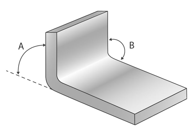
Similarly, bend angle is the angle formed at the web face that is held by the pad during L‑ or U‑bends.
Precautions in Pipe Bending
How hard a pipe is to bend depends on wall thickness, diameter, length, and material. Large or thick-walled pipes and tight radii increase cracking risk, so set a minimum bend radius for each size and steel grade.
Calculating the Developed Length for Pipe Bending
When pipe bending, run simulations to confirm the bend can be produced stably. These simulations should use a developed‑dimension calculation: the developed length of the bend is obtained from the distance between the bend center and the pipe’s neutral axis.
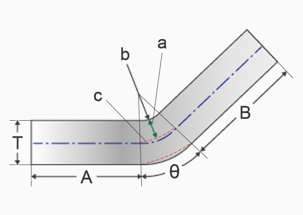
a: Distance from the bend radius to the neutral axis
b: Bend radius
c: Neutral axis of the bent section
For straight sections A and B, there is no change due to bending, so the original dimensions are used. The neutral axis shift rate for the bent section (λ, lambda) varies with material thickness, hardness, bend angle, and inner bend radius, but it is generally considered to lie around 20–45% of the pipe wall thickness. Because different steels tolerate different minimum bend radii, be sure to pick a radius that won’t cause cracking, check that the part can actually be bent as drawn, and choose the right steel.
L =A + B + ( R + T × λ ) × 2п × θ / 360
L: developed length
A・B: lengths of the sections without bending stress
R: inner bend radius
T: plate (wall) thickness
θ: bend angle
λ: neutral axis shift rate (%) *Empirical value is used.
Challenges of Conventional Pipe Bend Measurement
No matter what pipe bending process used, it’s difficult to completely avoid defects. Cracks, chipping, and form errors due to springback can lower yield rates and result in product quality issues or damage. Because of this, precise geometric inspection is required during all steps of production.

Challenges of Measurement with Calipers
Hand tools such as calipers can measure thickness and dimensions where they can physically clamp, but they cannot reach some locations, such as bent sections of a pipe.
Challenges of Measurement with a Profile Projector
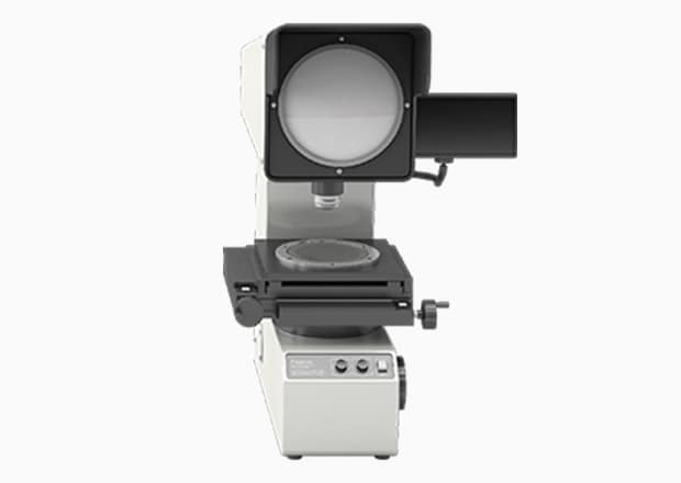
Projection comparators are often used to measure pipe‑bend profiles: the workpiece is placed on a stage and illuminated from below to project its outline onto a screen. The part must be carefully leveled when fixtured, and measurement results can vary with how the sample is positioned, so fixturing is time‑consuming and some shapes cannot be measured. For pipes with three‑dimensional bends, the setup must be changed for each measurement location, and large samples may not fit on the stage. In addition, the comparator does not directly provide numeric deviations from the drawing, and profiles sometimes must be traced onto paper, which complicates data storage and comparison.
Solutions for Challenges in Pipe Bend Measurement
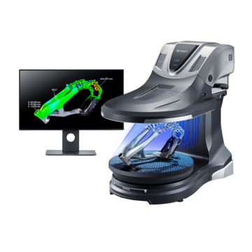
Conventional methods for measuring bent pipes struggle with three-dimensional geometries, making measurements slow and inconsistent. KEYENCE’s VL Series 3D Scanner CMM addresses these issues: it performs a one shot 360° scan of a pipe in as little as 8 seconds and captures complex 3D shapes with high accuracy. The VL Series accurately measures pipe bend dimensions, removes operator induced variability, and shortens inspection time.
Benefit 1: Easily Measure Bend Dimensions Regardless of Placement
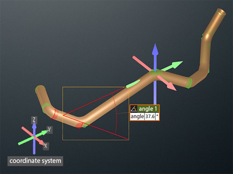
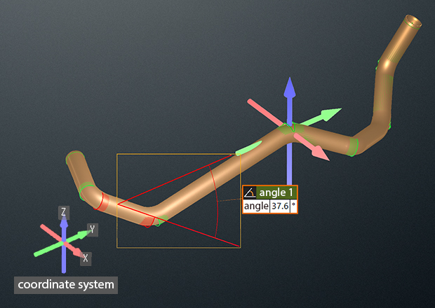
KEYENCE’s VL Series 3D Scanner CMM makes measuring 3D shapes like bent pipes simple. You can define an XYZ coordinate system and take measurements relative to that system. Unlike projection comparator methods that require repositioning the part for each measurement, the VL Series captures the entire object at once and lets you measure flexibly by changing the coordinate axes.
Benefit 2: Measure Complex Bent Pipes
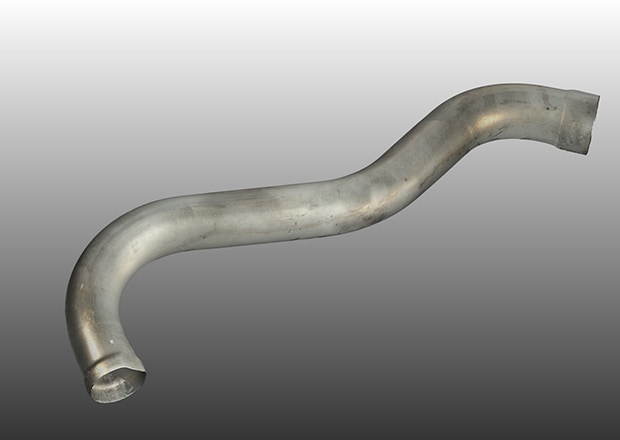
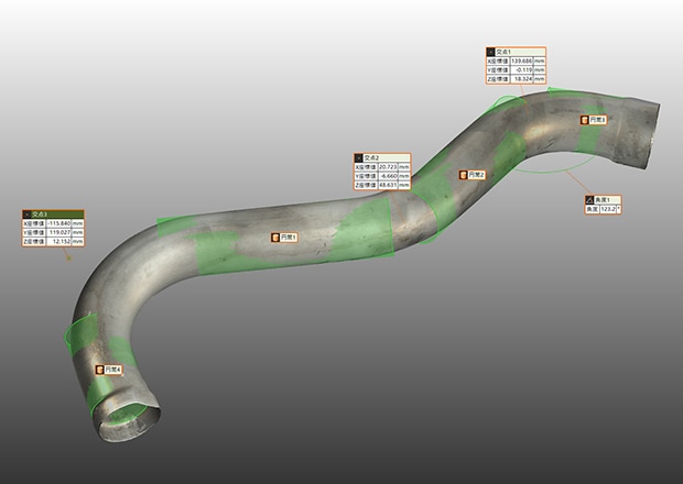
KEYENCE’s VL Series captures one shot scans to let you measure complex geometries quickly. The system handles XY measurements from constructed points, compares results directly with a CAD model, and makes defect detection and pass/fail decisions fast and reliable.
Achieve Accurate Pipe Bend Measurement in a Short Time
With KEYENCE’s VL Series 3D Scanner CMM, pipe bend dimensions can be measured easily, quickly, and accurately without repeatedly reorienting the sample, tracing profiles by hand, or manually comparing measurements to drawings.
- It captures a full 360° scan, so you don’t need to reposition the part for each measurement.
- A full 360° scan can be completed in minutes, greatly reducing inspection time.
- You can define an XYZ coordinate system freely on the scan, allowing measurement at any required location, even on complex shapes.
- Scans provide direct numeric measurements for each feature and enable quick comparisons to 3D CAD data.
Measurements that were once time consuming and labor intensive can be completed with KEYENCE’s VL Series 3D Scanner CMM in a single scan. Because required dimensions are readily accessible from the scan, inspections take far less time and overall work efficiency improves significantly.