Optical Comparator (Profile Projector)
Modular Measurement Systems: Picking the Best Setup
Key Takeaways
- Start system configuration by selecting a stage size (small, medium, or large) that matches your part's physical dimensions.
- Combine optical, laser, probe, and rotary modules to create a multisensor system that addresses specific, complex inspection needs.
- Choose a camera head based on tolerance: The IM Camera Head for >=+- 2 um tolerances, and the LM Camera Head for >=+-0.7 um needs.
- Leverage integrated data analysis, reporting, and network connectivity to feed measurement results directly into your quality systems.
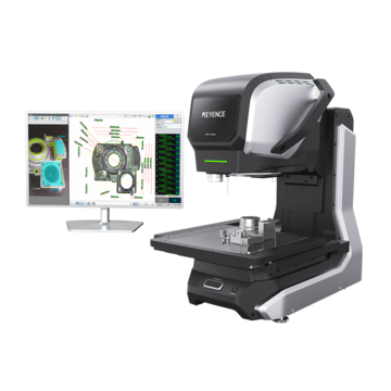
Dimensional measurement tolerance requirements are common across manufacturing applications, but the needs for each often differ. Compared to a massive stamped assembly, a precision turned component requires different inspection skills. This issue is resolved by the IM-X Series modular measurement system design , which enables producers to set up inspection capacity according to real requirements rather than acquiring capacities they might never utilize.
Choosing the appropriate mix of elements is the difficult part. A system's ability to handle your parts efficiently depends on a number of factors, including stage size, camera head specs, types of sensors , and software capabilities.
Start With the Part: Application Size
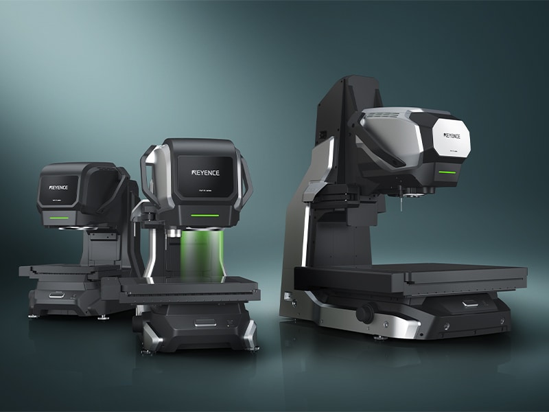
Physical dimensions set the first boundary condition for system configuration. The IM-X Series offers three-stage platforms that accommodate different measurement application size requirements.
The IM-X1220 tiny stage has a measurement area of up to 200 mm × 200 mm (7.87″ × 7.87″) and a height capacity of 150 mm (5.91″). This arrangement works well for small medical device parts, electrical assemblies, and precision-machined components. The IM-X1330 stage, which can handle most machined parts, castings, and assemblies, is useful for medium applications. It can measure up to 300 mm × 300 mm (11.81″ × 11.81″) and has a height range of 200 mm (7.87″).
The IM-X1540 stage, with its 500 mm × 400 mm (19.69″ × 15.75″) area and 200 mm (7.87″) height capability, is necessary for large part inspection. This envelope includes die-cast housings, automotive stampings, and aerospace structural components. The range of parts that can be examined internally is increased by the 3.3x increase in measurement area when compared to earlier generation systems.
Measurement range considerations go beyond only XY measurements. When measuring tall components, such as transmission housings or stacked assemblies, height capacity is important. Although they require more floor space and are initially more expensive, the larger the stage, the more parts can be measured in a single cycle.
What Each Module Adds (Optical, Laser, Probe, Rotary)
Combining various measurement technologies on a single platform results in a multisensor measurement system . Specific inspection requirements that other sensors are unable to adequately handle are addressed by each module.
The base optical system measures 2D features in the XY plane, such as hole diameters, edge positions, angles, and profile parameters, using a vision camera with a 20-megapixel CMOS sensor and configurable lighting. Optical measuring is fast and contactless, which makes it perfect for high-volume inspection, polished surfaces, and soft materials.
Non-contact height measuring with a small 50 μm spot diameter is made possible by the addition of the multi-color laser module. Step heights, flatness, warpage, and surface profiles are all measured by the laser. Rubber seals, sticky surfaces, and delicate finishes are among the materials handled by this sensor that cannot be touched.
Rotary measurement comes from the optional IM-XRU 360° unit that rotates parts while capturing continuous image data. This module measures circularity, cylindricity, coaxiality, and runout on cylindrical features like bearing journals, turned shafts, and machined bores.
The touch probe module brings true 3D contact measurement capability. With an ultra-low 0.015N measuring force, the probe touches surfaces to determine position in three-dimensional space. This enables measurement of angled faces, cone angles, perpendicularity between surfaces, and deep holes that cannot be seen by the camera.
Precision Needs: Wide Field vs. High-Precision Camera Heads
The choice of camera head balances the need for measurement precision against the field of view. Two field-upgradeable optics setups that serve distinct accuracy priorities are supported by the IM-X platform.
The High-Accuracy LM head provides tighter precision through increased magnification:
- 25 mm × 25 mm (0.98″ × 0.98″) field of view in wide-field mode (6 mm × 6 mm (0.24″ × 0.24″) in high-precision mode)
- 0.5 μm repeatability in wide-field mode, 0.1 μm in high-precision mode
he Wide-Field IM head uses a large 100 mm (3.94″) diameter lens to capture extensive areas:
- ø100 mm (ø3.94″) field of view (in wide-field mode)
- 1 μm repeatability within the field of view in wide-field mode
Both heads can be switched on-site without the need for specialized equipment and mounted to the same stage. When precise parts need to be verified, a shop may switch from using the IM head for general inspection to the LM head. Facilities can make the right investments by knowing when higher accuracy matters.
Tolerance requirements are directly related to head selection. The IM head usually works well with parts that have tolerances over ±5 microns. The improved precision of the LM head is advantageous for components that need tolerances of ±1 micron or less.
Beyond Optics: Multisensor Capabilities: Laser, Probe, and Rotary
Sensor integration turns a vision system into a complete multisensor measurement system . Any combination of measurement methods can work together in programmed sequences.
Consider a transmission casing made of die-cast. The mounting face distances and bolt hole locations are measured using the optical camera. In order to detect sink marks and verify flatness, the laser scans the mating surface. The touch probe confirms that the machined faces are perpendicular to one another. In a single software, everything operates automatically. Between steps, no operator is required.
Smart Assist automation improves focus, illumination, and edge detection for each sensor, making programming simpler. With intelligent parameter optimization and automated drawing import from DXF, PDF, or even actual drawings, it reduces program creation time by up to 80%. In order to make all surfaces appear focused in a single image, depth composition imaging combines several focal planes.
Data, Reporting, and Connectivity for QA/Manufacturing
Capturing dimensions is one thing. Getting that data into your quality systems and manufacturing processes in a useful way? That's what actually drives improvement instead of just generating paperwork.
The IM-X stores all measurement results automatically with full statistical analysis (average, standard deviation, 3σ, 6σ, Cpk values). Results include timestamps and lot identifiers for traceability without manual data entry. Hit one button, and inspection reports generate automatically.
Sharing configuration files across several systems is made possible via network connectivity. When a program is created on one IM-X unit, it spreads to the others. Regardless of whether inspection processes. By immediately connecting each inspection report to its modular measurement system program, QR code integration eliminates program selection errors.
The system exports results via USB or network for importing into statistical process control tools or enterprise quality systems.
Future-Proofing: Scaling From Bench to Line
Your measurement investment should grow with you, not force replacement when needs change. The modular architecture provides multiple paths for scaling capacity.
The modularity of the stage and head enables separate component upgrades. For urgent needs, a facility may begin with a tiny stage and a wide-field IM head. The same head and control system function with the larger stage as part sizes increase. Depending on the needs of the application, a rotary chuck can be added.
The small footprint is suitable for usage in a lab or on the shop floor. The IM-X operates in production settings, in contrast to huge CMMs that require climate control. By accounting for the thermal expansion of each material, built-in temperature correction preserves accuracy.
Machine operators can receive rapid feedback thanks to shop floor positioning. Instead of waiting for parts to get to a distant inspection department, quality problems emerge more rapidly when measuring stations are placed close to production equipment. The system's accuracy and extensive reporting features for process capability assessments and first article verification are advantageous to measurement lab setups.
Distributed inspection procedures can be implemented by networking multiple systems. Every operation on high-volume manufacturing lines may have an IM-X unit for in-process verification, with all data going into a central quality database.
It is necessary to match system capabilities to actual inspection requirements in order to choose the best configuration. The freedom to begin with fundamental capabilities and grow as needs change is made possible by modular architecture.
Contact KEYENCE today to get started with your modular measurement system and to configure your IM-X module set.

FAQs
How Should I Configure My IM-X System if My Budget Limits My Options?
Start by selecting a stage size that accommodates your largest typical parts. Then choose measurement heads based on your needs: optical for 2D features, laser for height verification, or touch probe for 3D geometry.
Does Module Choice Affect GR&R Outcomes Across Shifts?
Yes, you must use the same measurement head consistently. Switching between different measurement heads will produce varying results.
What’s the Break-Even Point for Adding a Rotary vs. Fixturing Time?
The majority of facilities that produce cylindrical parts achieve break-even in six to twelve months while improving their ability to measure circularity and coaxiality.