Optical Comparator (Profile Projector)
Gear Cutting Machine Applications and Processes
Gear cutting machines manufacture the tooth geometry on cylindrical blanks, enabling gears to transmit motion between rotating components.
Gear cutting is used in many industries, including the production of automotive transmissions, industrial reducers, and construction equipment. In these applications, the geometry of the tooth profile directly influences how loads are distributed as well as vibration and wear. Maintaining consistent machining conditions and verifying the resulting geometry are important parts of gear production.
Overview
Gears were made by hand from ancient times until the 18th century, when mechanization became widespread in Europe with the introduction of clocks and other machines. During the Industrial Revolution, machines dedicated to making gears were developed in quick succession.
In gear making, steel cylinders are first cut into circular plates, which are then machined into blanks (holed plates without teeth) before undergoing the processes of hobbing (cutting out teeth), quenching (heat treatment), and grinding of the surfaces and the teeth. Today, each process uses an NC gear manufacturing machine, such as a hobbing machine (machine for cutting out teeth). These gear manufacturing machines allow operators to easily adjust the cutting speed and to specify the number of gear teeth.
In recent years, composite processing machines based on lathes are becoming common. These composite processing machines can complete the processes from broaching (bore inner surface machining) and milling (cutting) to hobbing, minimizing changeovers and allowing for greater efficiency in gear production.
Major Types of Gears
Gears come in various shapes and sizes, and they all need dedicated machines for machining. Gears can be broadly categorized into spur gears and bevel gears, with spur gear cutting machines and bevel gear cutting machines as the specialized gear cutting machines, respectively.
Other gears include helical gears, which have spiral teeth; rack and pinion systems, which translate rotational motion to linear motion; and worm gears, which transfer motion in 90-degree angles.
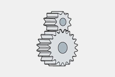
Spur types
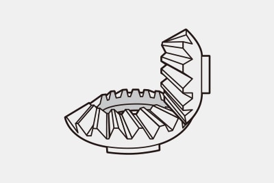
Bevel gear
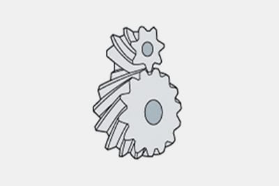
Helical gear
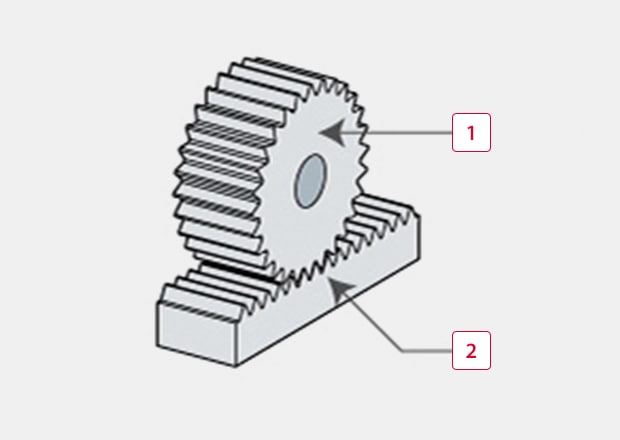
Rack and pinion
-
1Pinion
-
2Rack
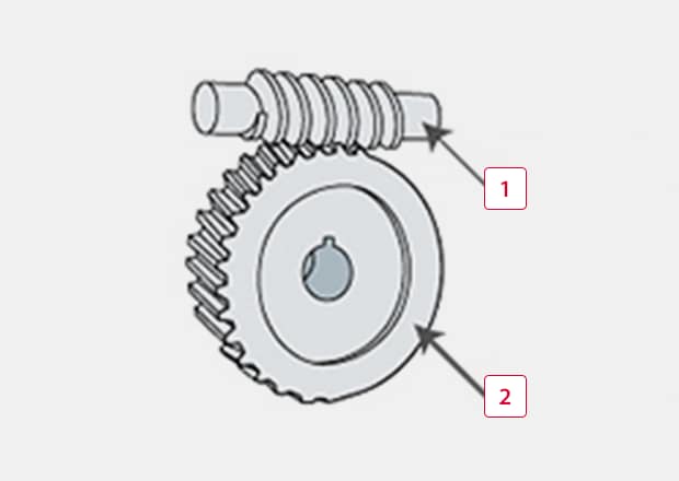
Worm and worm wheel
-
1Worm
-
2Worm wheel
Common Gear Cutting Methods
The most common methods of cutting gear teeth (hobbing) are the generating method and the forming method.
With the generating method, the rack cutter is pushed against the disk that will become a gear, cutting along the circumference of the disk. While this method makes it possible to produce high-precision gears, the high costs are a disadvantage. Precision parts can then be finished by grinding or honing after the teeth have been cut. The generating method is widely adopted in gear cutting, and the most common machine used is the hobbing machine.
On the other hand, the forming method uses a milling machine equipped with a cutting tool with the same shape as the grooves of the desired gear. This method enables mass production of gears without the need for dedicated production machines.
Other ways of making gears include shaping for producing bevel gears, and plastic forming processes such as forging.
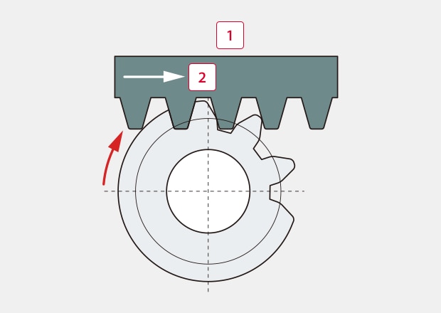
Image of Gear Cutting by Generating Method
-
1Rack cutter
-
2Direction of travel of teeth
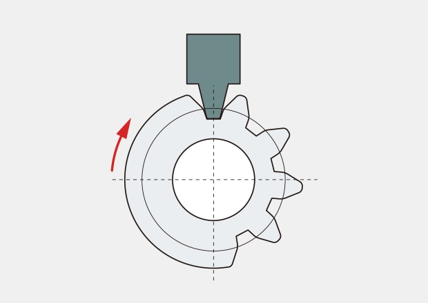
Image of Gear Cutting by Forming Method
Each groove is cut using a specialized tool bit attached to the milling machine
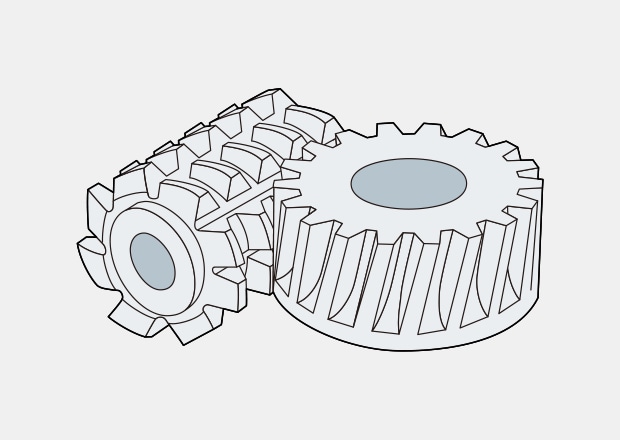
Schematic illustration of gear cutting using a hob
NC Gear Production Machines
Among the many NC gear production machines, the NC hobbing machine is one of the most widely used types and is widely employed in the automobile industry. Numerous models have been developed in the pursuit of precision and production efficiency, further empowering gear production.
Other NC gear production machines include shaping machines, which can achieve precision teeth cutting; grinding machines, which grind quenched gears; honing machines, which scrub the surface of gears after quenching; and shaving machines, which finish the gears. These machines are all used to produce precision gears.
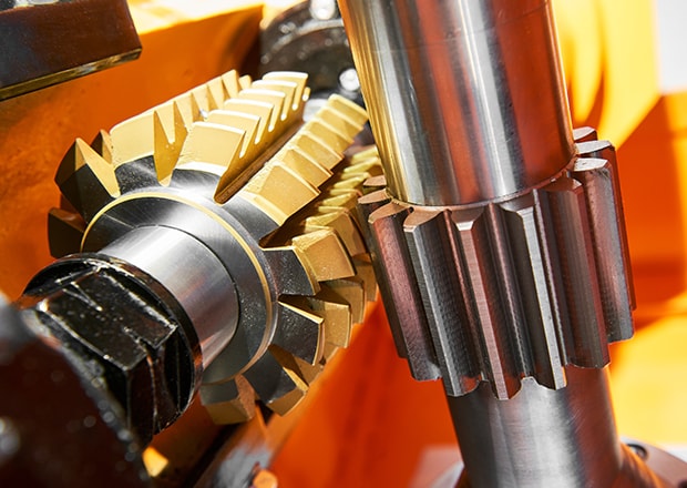
Types of Gear Cutting Machines
Different gear cutting machines are used for different geometries and production methods. Common machines used in gear cutting include:
- Hobbing machines
- Shaping machines
- Broaching equipment
- Milling machines
Each machine produces the tooth profile through a different cutting motion. High-volume gear manufacturing environments often rely on dedicated gear cutting machines that are designed for repeatable production. Flexible machining systems may also be used when multiple gear types are all produced on the same equipment.
Gear Hobbing and Gear Shaping Methods
Gear hobbing and gear shaping are two widely used processes for creating gear teeth.
Gear hobbing uses a rotating cutting tool called a hob. The hob and the gear blank rotate in sync while the cutter advances across the surface of the workpiece. This continuous cutting action helps create the space between the teeth and is commonly used for external spur and helical gears.
Gear shaping, on the other hand, uses a cutter that is shaped like a gear. The cutter moves vertically while the gear blank rotates in coordination with the tool. This process gradually generates the tooth geometry inside the gear blank. Gear shaping is commonly used for internal gears or components where the geometry would be limited by the use of a hob.
CNC Gear Cutting Technology
CNC gear cutting machines coordinate spindle rotation and tool movement through programmable machine control. Cutting parameters such as feed rate and tool motion are controlled via software.
This programmable control allows machining conditions to remain consistent across the production cycle. CNC systems also allow operators to adjust cutting programs when different hear designs must be produced on the same machine.
Machining Gears for Precision Performance
Machining gears begins with the preparation of the gear blank so that reference surfaces can support accurate cutting. Features such as the bore and end face are commonly used to align the workpiece during cutting.
After the teeth have been created, gears may undergo heat treatment to increase hardness and improve wear resistance. Heat treatments can introduce dimensional changes in the tooth geometry, and so additional processing, like grinding or honing, may be needed to refine the tooth's surface and restore the intended profile.
Gear Inspection and Profile Measurement
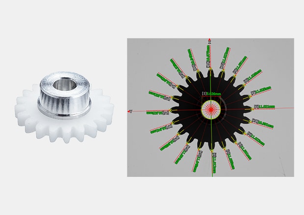
After machining, gear inspection verifies that the tooth profile matches the intended geometry. Measurement systems capture data (like tooth profile accuracy, spacing, and runout) from the gear surface and determine if the newly produced gear passes inspection. This step allows manufacturers to identify profile variation before the gears are allowed to move into assembly.
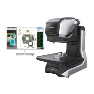
Optical measurement systems are commonly used for quick dimensional inspection. The KEYENCE IM-X Series allows production teams to measure multiple dimensions of machined components quickly. Additionally, the system supports automated inspection across batches of parts, offering inspection on up to 1,000 parts at once. The system also offers a swappable camera head with high-resolution geometry data for more complex components.
Improving Accuracy in Gear Manufacturing
Verifying that cut gears maintain their dimensional accuracy during gear shaping and production requires coordination between machining operations and measurement results.
Tool wear and machine alignment all influence the resulting tooth geometry. Production teams often monitor inspection data to look out for variations during manufacturing. If operators spot issues with dimensions, they can adjust the parameters or tooling before any additional parts are produced.
Stable conditions also improve inspection reliability. Factors that can impact the quality of a cut gear can be as simple as temperature variations or vibrations, which can influence dimensional readings when tolerances are tight. Maintaining controlled inspection environments allows manufacturers to evaluate and inspect gears consistently to support production stability.
Improve gear cutting machine performance and verify gear accuracy with advanced measurement and inspection solutions from KEYENCE.