Optical Comparator (Profile Projector)
Measurement Fundamentals: What Is Tolerance?
Key Takeaways
- Tolerance defines allowable deviation from a nominal dimension, e.g., 100 mm ±0.5 mm (3.94″ ±0.02″).
- Dimensional tolerances govern size features and are communicated as ± or limits on drawings.
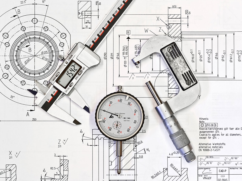
- Inspection compares measured values to tolerance limits using calipers, CMMs, micrometers.
- Geometric tolerancing controls form/position (flatness, location) beyond simple size limits.
Tolerance is the allowable range of variation from a stated dimension. Since no manufactured part is exactly as drawn, tolerance defines how much deviation is acceptable before a part's performance suffers, allowing for production and assembly.
Definition of Tolerance Range
The definition of the tolerance range starts with the base value. This is the target dimension that is shown on the original drawing before production. From there, there are upper and lower limits that define how far a measurement can deviate while remaining acceptable.
For example, a nominal dimension of 100 mm (3.94″) with a tolerance of ±0.5 mm (±0.02″) creates an acceptable range from 99.5 mm to 100.5 mm (3.92″ to 3.96″). The tolerance range is the difference between the two limits and communicates to both the manufacturing and inspection teams what outcomes are acceptable.
In practice, this range is determined based on the part function. Where a loose range may be acceptable for non-critical features, tighter limits may be applied where parts have to sit flush together or must align within a narrow space.
Dimensional Tolerance in Measurement Fundamentals
Dimensional tolerance focuses on size-based features such as length, depth, diameter, and thickness. These tolerances help define how much a physical measurement can vary while still meeting design intent.
How Dimensional Tolerance is Applied
On engineering drawings, dimensional tolerance appears alongside a state value. It may be shown as a plus/minus value or as a defined, exact limit. The format of the tolerance may vary, but the goal remains the same: to communicate the acceptable range of measurements within a window.
Manufacturing processes rarely produce identical results across every part. Tool wear and material behavior all influence the final measurements of the part, but as long as those parts fall within the dimensional tolerances, those variables can be accepted without requiring additional rework.
How Dimensional Tolerance is Measured
Inspection relies on tools that are suited for the feature being evaluated. Common examples include calipers, micrometers, and height gauges. For more complex parts, coordinate measuring machines capture detailed dimensional data. Measurements are also not limited to collecting values. Inspectors interpret those values against the tolerance limits, so if a part differs slightly from its nominal size, it can still pass inspection if it remains within the acceptable range.
Tolerance Limits in Engineering Applications
Tolerance limits play a direct role in how parts interact with each other. This becomes clear in assemblies where multiple components must fit together.
One common framework for understanding this is the concept of fits:
- Clearance fit: The shaft is always smaller than the hole, leaving space between the parts
- Transition fit: Depends on variation, but parts may fit loosely or require very light force to seat
- Interference fit: The shaft is always larger and requires force during assembly
Each fit type depends on how tolerance limits are defined for mating features. Small changes in those limits can shift how parts behave during assembly or operation.
Tolerance also affects production cost. Tighter limits often require more precise processes or additional inspection steps. For that reason, tolerances are typically applied based on the functional need of the part instead of uniform tightness across all features.
The Role of Geometric Tolerancing in Precision Measurement
Dimensional tolerance addresses size, but it does not fully describe how a feature exists in space. This is where geometric tolerancing comes into play. It defines acceptable variation in form and position.
Why Geometric Tolerancing is Used
A part may meet its dimensional tolerance and still fail during assembly. A hole may have the correct diameter but sit slightly out of position. A surface may meet thickness requirements but lack the needed flatness. These conditions affect performance even when size appears correct.
Geometric tolerancing addresses these issues by controlling how features relate to one another, and it allows designers to describe how a part should function, not just how large it should be.
How it Connects to Measurement
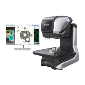
Geometric tolerancing also guides inspection. Measurement systems, like those from KEYENCE, evaluate characteristics like flatness and straightness, along with feature position and surface profile relative to the defined tolerances.
Explore precision measurement solutions to control and verify tolerances with confidence. Contact KEYENCE today.