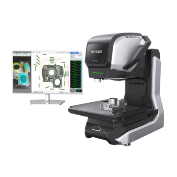
Optical Comparator (Profile Projector)
Formula for Cutting Speed in Milling
Key Takeaways
- Cutting speed (vc) is determined by tool diameter and spindle speed; always recalculate when changing tool sizes to maintain consistent performance.
- Feed rate (vf) must be balanced with spindle speed and the number of teeth to ensure proper chip load and prevent excessive heat generation.
- Machining time (Tc) is calculated using the total feed length (material length + cutter diameter) divided by the table feed rate.
- Net power (Pc) requirements depend on material-specific cutting force (Kc), depth/width of cut, and machine efficiency.
When it comes to cutting speeds, the formula defines how quickly the cutting edge of the tool moves across the surface of a material during milling. This value is measured at the outer edge of the tool rather than at the spindle, which means it reflects the actual contact with the workpiece.
In face milling, any formula for cutting speed is calculated using the relationship between tool diameter and spindle rotation.
The standard formula is:

π (3.14): Circular constant
DC (mm): Cutter diameter
n (min-1): Spindle speed
This formula is used to calculate the cutting speed from the spindle speed and the outer diameter of the cutter.
Example:
Cutter diameter (DC) = 100 mm
Spindle speed (n) = 400 min-1
In this case, the cutting speed (vc) is approximately 125.6 m/min.
Increasing the spindle speed (n) or using a larger tool (DC) raises the resulting cutting speed (VC). A larger cutter travels a greater distance per rotation, which raises surface speed even if the rotations per minute (RPM) stay the same. Because of this, cutting speed must always be calculated using the actual tool size in use.
Cutting speeds for milling are not selected in isolation. These speeds are tied to the material being cut and the overall condition of the tool. Softer materials can typically support higher cutting speeds, while harder materials require a lower speed to reduce heat and wear down the tooling edge.
Cutting Speed for Milling: Key Concepts
Cutting speed for milling is the distance the cutting edge travels over time; it is typically expressed in meters per minute (m/min) or SFM (surface feet per minute), depending on geographical region and the machine setup.
This value is influenced by both the tool geometry and operating conditions. Tool diameter directly affects how far the edge of the cutting tool travels during one revolution, and spindle speed determines how many times that rotation occurs each minute. These two variables work together to define the final cutting speed.
Changes in diameter can quickly change the cutting speed of a face milling process. A small reduction in tool size increases the required spindle speed to maintain the same surface speed. If the spindle speed is not adjusted, the cutting speed drops, which then affects cutting performance and surface finish.
Cutting speed also affects how tools behave during machining. Higher speeds can improve material removal rates, but they also increase the heat generated along the cutting edge. Lower speeds help reduce that thermal load, but may lead to longer cycle times. Finding a balance between speed and tool behavior will allow the tool to cut through material quickly and cleanly while maintaining stable conditions.
How to Calculate Spindle Speed
Spindle speed is calculated based on the desired cutting speed. The process begins with a target cutting speed that is based on material and tooling, and then it converts that value into revolutions per minute.
The formula used to calculate spindle speed is:

This equation shows that spindle speed (n) depends on both cutting speed (VC) and tool diameter (D or DC). Smaller tools require higher RPMs to reach the same cutting speed because each rotation covers less distance. Larger tools require lower RPM for the same reason.
This relationship becomes important when the tool size changes during an operation. If the diameter is reduced and the spindle speed remains unchanged, then the cutting speed will also decrease.
This change in cutting speed can lead to inconsistent cutting behavior, especially in operations where surface finish is a priority. Because of this, spindle speed should always be recalculated when the tool diameter changes rather than being reused from previous setups.
Feed per Tooth (f)

vf (mm/min): Table feed per minute
z: Number of teeth
n (min-1): Spindle speed (Feed rate fr = zxfz)
This formula is used to calculate the feed per tooth from the table feed per minute (feed rate), the number of teeth, and the spindle speed.
Example:
Table feed per minute (vf) = 450 mm/min
Number of teeth (z) = 10
Spindle speed (n) = 600 min-1
In this case, the feed per tooth (f) is 0.075 mm/t.
Feed Rate Formula for Face Milling
Feed rate describes how fast the cutting tool moves across the surface of the workpiece; while cutting speed describes rotational motion at the edge, feed rate describes the linear movement across the material.
The feed rate formula for milling is:

fz (mm/tooth): Feed per tooth
z: Number of teeth
n (min-1): Spindle speed (Feed rate fr = zxfz)
This formula is used to calculate the table feed per minute (feed rate) from the feed per tooth, the number of teeth, and the spindle speed.
Example:
Feed per tooth (fz) = 0.2 mm/tooth
Number of teeth (z) = 8
Spindle speed (n) = 600 min-1
In this case, the table feed rate is 960 mm/min.
Feed per tooth determines how much material each tool insertion removes during a single pass. When the spindle speed increases, each cutting edge engages the material more frequently, which raises the overall feed rate. Increasing the number of cutting tools also has a similar effect.
The feed rate has to stay in line with the spindle speed in order to maintain a consistent chip load or material removal. If the feed is too low relative to the RPM, the cutting edge may not interact with the material properly. This can lead to excess heat at the tool's surface. However, with the right balance, each interaction removes material evenly.
Machining Time (Tc)

L (mm): Total table feed length (Length of material (l) + Face mill diameter (DC))
vf (mm/min): Table feed per minute
This formula is used to calculate the machining time from the total table feed length and the table feed per minute (feed rate).
Example of finishing a block of FC200 cast iron to have a flat surface of:
Width = 150 m
Length = 250 mm
Face milling conditions used:
Feed per tooth (fz) = 0.35 mm
Number of teeth (z) = 12
Spindle speed (n) = 200 min-1
Cutting speed (vc) = 120 m/min
Face mill diameter (D1) = 220 mm
In this case,
the table feed per minute (vf) and the total table feed length (L) are:
vf = 0.35 × 12 × 200 = 840 mm/min
L = 350 + 220 = 570 mm
Substitute these values into the formula:
Tc = L ÷ vf
= 570 ÷ 1120
= 0.679 (min) × 60
= 40.74 (sec)
The machining time (Tc) is approximately 40.74 seconds.
Net Power (Pc)

ap (mm): Depth of cut
ae (mm): Width of cut
vf (mm/min): Table feed per minute
Kc (MPa): Specific cutting force
η: Machine efficiency
This formula is used to calculate the net power required for face milling based on the depth and width of cut, the table feed per minute, the specific cutting force, and the machine efficiency. Example of calculating the net power required to cut tool steel with:
Depth of cut (ap) = 5 mm
Width of cut (ae) = 70 mm
Table feed per minute (vf) = 300 mm/min
Other conditions:
Specific cutting force (Kc) = 1800 MPa
Machine efficiency (η) = 80% (0.8)
Cutting speed (vc) = 80 m/min
Cutter diameter (DC) = 250 mm
Number of teeth (z) = 16
In this case, first you calculate the spindle speed (n) and then the feed per tooth of the cutter (fz).
Spindle speed (n) = 1000・vc ÷ π・D
= (1000 × 80) ÷ (3.14 × 250)
= 101.91 min-1
Feed per tooth (fz) = vf ÷ (Z × n)
= 300 ÷ (16 × 101.91)
= 0.184 mm/tooth
Substitute the above into the formula:
Pc = (5 × 70 × 300 × 1800) ÷ (60 × 106× 0.8)
= 3.937 kw
The net power required for face milling (Pc) is approximately 3.94 kW.
Kc Values
| Workpiece material | Tensile strength (MPa) and stiffness | Specific cutting force Kc (MPa) for each feed | ||||
|---|---|---|---|---|---|---|
| 0.1 (mm/tooth) | 0.2 (mm/tooth) | 0.3 (mm/tooth) | 0.4 (mm/tooth) | 0.6 (mm/tooth) | ||
| Mild steel (SS400, S10C, etc.) | 520 | 2200 | 1950 | 1820 | 1700 | 1580 |
| Medium steel (S45C, S50C, etc.) | 620 | 1980 | 1800 | 1730 | 1600 | 1570 |
| Hard steel (S55C, S58C, etc.) | 720 | 2520 | 2200 | 2040 | 1850 | 1740 |
| Tool steel (Carbon tool steel (SK), etc.) | 670 | 1980 | 1800 | 1730 | 1700 | 1600 |
| Tool steel (Alloy tool steel (SKS), etc.) | 770 | 2030 | 1800 | 1750 | 1700 | 1580 |
| Chrome-manganese steel (Manganese carbide (MnC), etc.) | 770 | 2300 | 2000 | 1880 | 1750 | 1660 |
| Chrome-manganese steel (Manganese carbide (MnC), etc.) | 630 | 2750 | 2300 | 2060 | 1800 | 1780 |
| Chrome molybdenum steel (SCM grades, etc.) | 730 | 2540 | 2250 | 2140 | 2000 | 1800 |
| Chrome molybdenum steel (SCM grades, etc.) | 600 | 2180 | 2000 | 1860 | 1800 | 1670 |
| Nickel chrome molybdenum steel (SNCM415, etc.) | 940 | 2000 | 1800 | 1680 | 1600 | 1500 |
| Nickel chrome molybdenum steel (SNCM439, etc.) | 352HB | 2100 | 1900 | 1760 | 1700 | 1530 |
| Austenitic stainless steel (SUS304, etc.) | 155HB | 2030 | 1970 | 1900 | 1770 | 1710 |
| Cast steel (SCC, etc.) | 520 | 2800 | 2500 | 2320 | 2200 | 2040 |
| Hard cast iron | 46HRC | 3000 | 2700 | 2500 | 2400 | 2200 |
| Meehanite cast iron (FC350, etc.) | 360 | 2180 | 2000 | 1750 | 1600 | 1470 |
| Gray cast iron (FC250, etc.) | 200HB | 1750 | 1400 | 1240 | 1050 | 970 |
| Brass (C3710, etc.) | 500 | 1150 | 950 | 800 | 700 | 630 |
| Light alloy (Al-Mg, A5005, etc.) | 160 | 580 | 480 | 400 | 350 | 320 |
| Light alloy (Al-Si, A4032, etc.) | 200 | 700 | 600 | 490 | 450 | 390 |
| Light alloy (Al-Zn-Mg-Cu, A7075, etc.) | 570 | 880 | 840 | 840 | 810 | 720 |
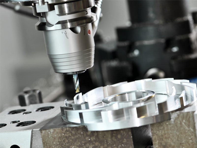
Improve machining accuracy with advanced measurement systems for milling applications.

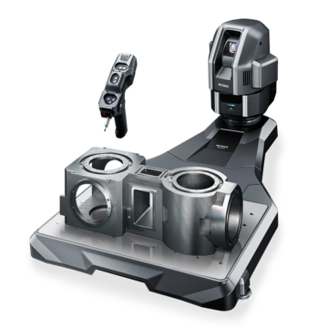
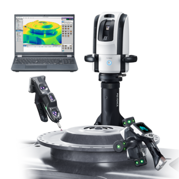
Related Products
Related Downloads
-

XM Series Handheld Probe Coordinate Measuring Machine Catalog
Brochure for the XM-5000 Series Handheld CMM. Portable CMM to easily and accurately measure 3D and GD&T features anywhere including the shop floor and in the machine tool.
-

WM-6000 series Wide Area CMM Catalog
Brochure for the WM-6000 series Wide-Area CMM. A portable setup with a wireless handheld probe that enables users measure large parts and equipment.