CMM (Coordinate Measuring Machine)
How CAD Enables Quicker Inspection Set-Up
Key Takeaways
- Reduce inspection setup time from hours to minutes by directly loading CAD files, eliminating drawing interpretation errors.
- Achieve consistent, repeatable results by automating measurement programs from CAD data, eliminating operator variability.
- Enable real-time quality control with faster inspection, detecting process deviations early to reduce scrap and improve efficiency.
- Visually identify deviations from nominal dimensions by superimposing results on the CAD model with color-coded deviation maps.
Translating design intent into measurement procedures that confirm parts meet requirements is a frequent challenge for quality inspectors. Understanding and interpreting the drawing between departments, tolerance definition, measurement point programming, and routine creation can be a complex mechanism to navigate in order to properly inspect parts, especially when using traditional inspection tools like hand tools, optical comparators, and CMMs. For challenging components, this procedure takes hours or even days. CAD integration changes this dynamic completely by transforming how measurement systems understand and evaluate manufactured parts.
When digital design files connect directly with measurement equipment, the inspection process speeds up dramatically. Programs that previously required extensive manual input now generate automatically from existing CAD data. This connection between design and verification eliminates redundant work while maintaining the accuracy and CAD quality control that users demand.
What is a CAD Model, and What is it Used for in Inspection?
A CAD model represents a digital blueprint of a part, containing complete geometric information about surfaces, features, and dimensions. During the design stage, engineers use programs like AutoCAD, SolidWorks, Fusion 360, CATIA, or NX to create these files, which capture each component's intended form.
CAD models are used as the benchmark for comparing manufactured parts in inspection applications. Instead of programming measurement routines by manually identifying points and establishing coordinate systems, operators simply load the CAD file and let the system extract necessary information.
This approach eliminates interpretation errors that occur when translating 2D drawings into measurement programs. The 3D model contains complete geometric truth without ambiguity. Without the need for human input, the software automatically detects characteristics like holes, slots, bosses, and other components. The intelligent distribution of measurement points across surfaces guarantees sufficient coverage for statistical analysis.
KEYENCE Benefits for Leveraging CAD
KEYENCE measurement systems significantly simplify CAD quality control. The solution removes the hassles associated with file conversion by immediately reading typical CAD files. Design files move seamlessly from engineering to quality thanks to DXF, STEP, IGES, and native format support.
For complicated parts, setup times are reduced from hours to minutes. Using basic reference features, the system aligns the CAD model to the actual part. Measurement software uses the geometric data in the design file to automatically run after alignment. In product lines where dozens or hundreds of parts need to be regularly verified, this speed benefit multiplies.
When the measurement process is driven by CAD, repeatability improves. Because the system uses the same digital source, all inspections follow the same protocols. Regardless of who operates the system, operator variability vanishes, guaranteeing consistent output. This consistency matters for trend analysis and process control, where data comparability is paramount.
The coordinate measuring machine technology from KEYENCE handles CAD-based inspection across different system configurations. The CAD integration is the same whether optical, touch probe, or 3D laser scanning techniques are used. Once measurement routines are established, engineers can use them across several inspection stations without having to modify them.
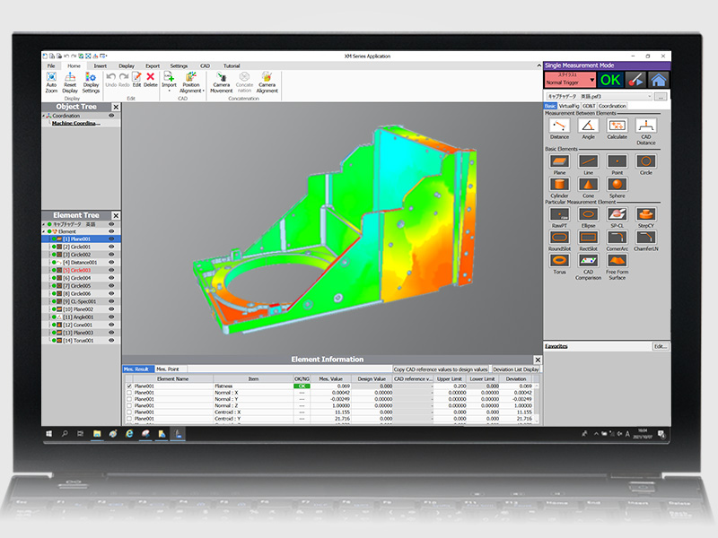
Visual comparison tools also use color-coded deviation maps to superimpose measurement results on the CAD model. Where parts vary from nominal dimensions is immediately apparent thanks to these displays. Quality engineers can easily identify trends and patterns that numerical data tables may hide.
The Impact of CAD on Manufacturing Efficiency
Production schedules benefit significantly when inspection keeps pace with manufacturing output. Once bottlenecked throughput, manufacturing accuracy verification now occurs quickly enough to enable high-volume operations. Without piling up in lines to wait for measurement procedures, parts pass through CAD quality control inspections.
First article inspection becomes faster and more thorough. New parts or engineering changes require verification before full production begins. CAD-based systems validate complete part geometry in a fraction of the time manual programming demands. This speed reduces the lag between design release and production ramp-up.
Engineering changes flow through the system smoothly when CAD files are updated. Rather than rewriting measurement programs from scratch, operators load the revised CAD model, and the system adapts automatically. Where designs evolve frequently based on testing or customer feedback, this flexibility supports agile manufacturing settings.
How CAD Reduces Errors in Production
One major cause of quality system failures is programming flaws. Errors and misunderstandings occur when operators manually define measurement sequences or enter coordinates. Quality control systems that extract information directly from CAD files eliminate this human error factor almost entirely.
The automated feature recognition in CAD-driven inspection catches geometry that manual programming might miss. Complex surfaces and subtle blend radii are measured comprehensively rather than sampled at a few points. This comprehensive assessment gives assurance that components fulfill requirements over their whole geometry.
Real-time quality control feedback becomes practical when setup time shrinks. Instead of using batched end-of-day inspection cycles, parts might be measured during or right after manufacturing processes.
Faster feedback loops often mean process deviations get detected and corrected before significant scrap accumulates.
How KEYENCE Measurement Systems Integrates CAD for Improved Inspection Process
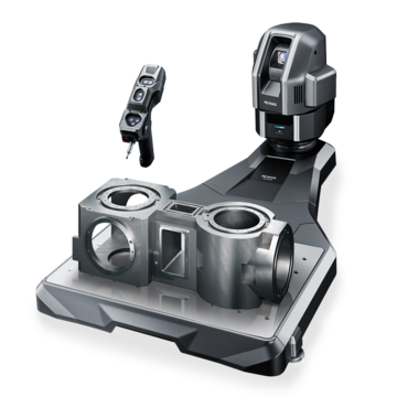
The XM Series brings CAD-based inspection to benchtop coordinate measuring machines. These systems handle small to medium parts with non-contact measurement that won't damage delicate features. The optical technology scans complete part profiles in seconds, comparing results against CAD geometry automatically.
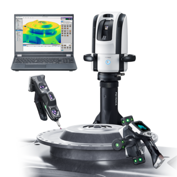
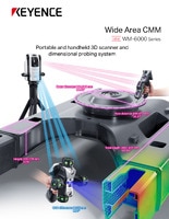
For larger parts, assemblies, or equipment, the WM Series provides wide-area measurement while maintaining CAD integration benefits, including even more enablement with the handheld 3D laser scanner to compare more data points to the CAD files. These systems inspect assemblies and structural components where traditional CMMs struggle with size or weight limitations.
Complex parts with difficult access requirements work well with portable arm CMM solutions. The articulated arm brings measurement capabilities directly to the part rather than requiring transport to a dedicated inspection room. CAD models guide the measurement process even in these flexible configurations.
Software intelligence handles surface alignment without requiring precise part placement. The system identifies features in the CAD model, locates corresponding features on the physical part, and calculates the transformation automatically. This best-fit alignment compensates for reasonable positioning variations, making setup faster and more forgiving.
Report generation happens automatically after measurement completes. Templates that make reference to CAD model features are used to create results tables, deviation charts, and color maps. Automated reports are consistent, which shortens review times and enhances stakeholder communication.
Tools for trend analysis monitor changes in measurable dimensions over production runs. Statistical process control charts make reference to consistent targets when CAD specifies the nominal values. Process engineers identify tool wear, thermal effects, or material variations before they cause out-of-specification parts.
Contact KEYENCE today to improve your quality control process with CAD integration.

FAQs
How Does CAD Integration Improve Real-Time Quality Control?
CAD integration drastically cuts setup time, allowing parts to be measured immediately after production rather than in delayed batch cycles. The expedited program creation means inspection keeps pace with manufacturing speed. Visual deviation displays make problems obvious instantly, enabling quick corrective action.
What KEYENCE Systems Offer CAD-Based Quality Control Solutions?
CAD integration is supported by all of KEYENCE measuring equipment, including portable arm solutions and benchtop optical CMMs. The XM Series uses non-contact scanning to do accurate, tiny part inspection. The WM Series supports larger assemblies and components. CAD-based measurement is brought straight to factory floors or field sites with portable arm CMMs.
How Can CAD Use in QC Reduce Production Errors?
Programming errors that arise during the creation of manual measurement routines are eliminated via CAD-driven inspection. Complete part evaluation without missing dimensions is ensured by automated feature identification. The visual comparison between CAD and measured data makes deviations obvious before parts ship. Real-time process feedback is made possible by faster inspection cycles, which help identify issues early.

Related Products
Related Downloads
-
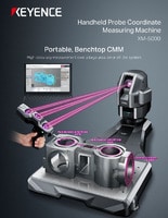
XM Series Handheld Probe Coordinate Measuring Machine Catalog
Brochure for the XM-5000 Series Handheld CMM. Portable CMM to easily and accurately measure 3D and GD&T features anywhere including the shop floor and in the machine tool.
-
WM-6000 series Wide Area CMM Catalog
Brochure for the WM-6000 series Wide-Area CMM. A portable setup with a wireless handheld probe that enables users measure large parts and equipment.
