CMM (Coordinate Measuring Machine)
GD&T Benefits and Capabilities
Key Takeaways
- GD&T provides a universal language for precise geometry, reducing design ambiguity and manufacturing errors.
- Datums are reference points for measurements. Their correct selection and precedence are vital for accurate, repeatable inspections.
- GD&T is critical in aerospace, medical, and automotive for ensuring component safety, functionality, and precise integration.
- Understanding GD&T symbols for flatness, position, and runout is key to controlling part quality and ensuring proper function.
It can be challenging to fully understand all GD&T symbols and standards while also correctly interpreting dimensional tolerances. Therefore, we simplified GD&T by focusing on practical interpretation and measurement. The explanations are based on the ISO standard and also highlight key differences with ASME.
GD&T basics and measurement are necessary for both current and future product manufacturing.
We will guide you through this area.
What is GD&T and Why is it Crucial for Precision Engineering?
GD&T, or Geometric Dimensioning and Tolerancing, provides a universal language that defines precise part geometry. This standardized system goes beyond basic measurements to specify how features relate to each other and function within assemblies. Unlike traditional methods that only capture length and width, GD&T establishes clear boundaries for form, orientation, and location.
Manufacturing teams use GD&T to reduce ambiguity in design. When everyone interprets drawings the same way, production errors drop significantly. This clarity becomes essential when parts must fit together perfectly or when components travel between multiple facilities. GD&T also helps identify which dimensions matter most for functionality, allowing inspectors to focus their efforts where quality truly counts.

Decoding GD&T Symbols
GD&T symbols replace wordy descriptions with visual indicators that define tolerance limits. Flatness ensures surfaces remain even without warping. Perpendicularity ensures that features form a true 90-degree angle to their reference surfaces or datums. Position tolerance establishes zones where bolt holes or pins can exist, critical when components must fit together precisely. KEYENCE coordinate measuring machine systems verify these specifications quickly, easily, and accurately.
Learning to interpret these markings takes some time, but it pays off . Runout symbols, shown as arrows in circles, control how smoothly shafts or cylinders rotate. Parallelism ensures that opposing surfaces remain an equal distance apart. Concentricity aligns circular elements around shared centerlines. Grasping GD&T symbology means understanding how each control safeguards performance while allowing realistic production variance.
Together, the various tolerance classes describe the behavior of the entire part. Profile tolerances regulate complex curved surfaces, such as those in cast or molded parts. Angularity defines the precise angle between surfaces, essential for tapered or wedge connections. Cylindrical features are required to stay round throughout. Designers know when basic callouts are acceptable for less critical regions.
Understanding Datums and Datum Systems
Datums serve as reference points for all measurements. Think of them as the pillars that support your inspection process. A basic datum, often the largest or most stable surface, establishes the first plane of reference. Secondary and tertiary datums then constrain the remaining degrees of freedom, creating a complete coordinate system.
The right choice of datum determines how geometric and dimensional tolerances relate to one another. Choose datums that closely resemble the mounting or mating of parts in actual applications.
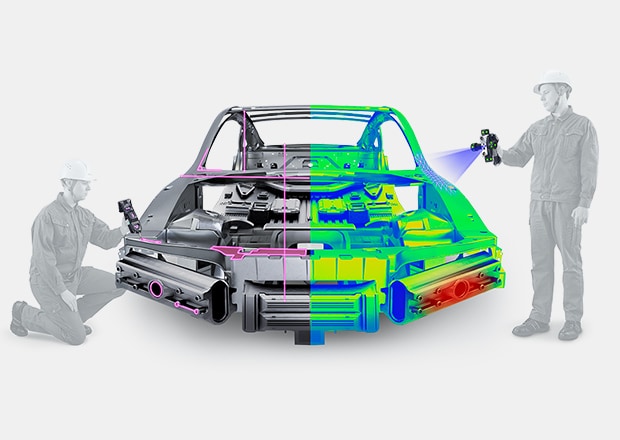
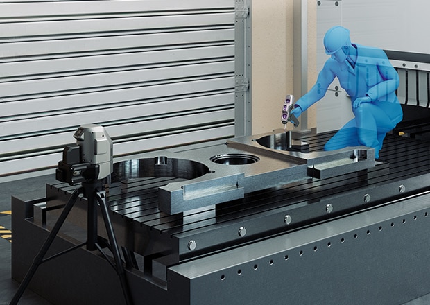
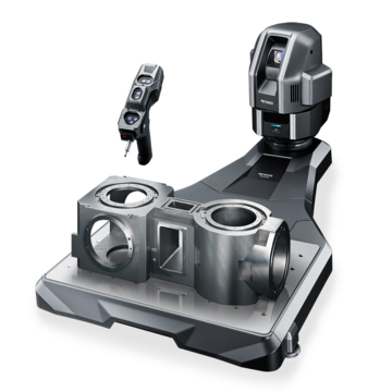
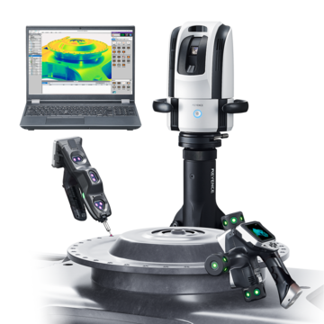
The WM Series excels at establishing these reference frames quickly. Datum systems prevent misinterpretation across different facilities and suppliers. As an example, if Tokyo builds one half of an assembly and Chicago builds the other, both teams must reference identical datums for seamless integration.
Datum precedence is more important than most people think. The order in which datums are applied has a direct impact on measurement results. Start with the surface that provides the most stability, then add references that constrain rotation and lateral movement. Errors in the datum hierarchy cause acceptable parts to be rejected or allow defective parts to evade inspection, cascading through each succeeding measurement. Consistency between operators and shifts is ensured by documenting your datum strategy.
Get detailed information on our products by downloading our catalog.
View Catalog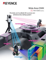

Applications of GD&T in Manufacturing
Aerospace components demand extreme accuracy, making the basics of GD&T essential for flight safety. Turbine blades require a precise geometric tolerance position to maintain balance at high speeds. Medical devices rely on consistent geometric tolerance and dimensional tolerance specifications to ensure patient safety. Even consumer electronics benefit from these standards as phones grow thinner and tolerances tighten.
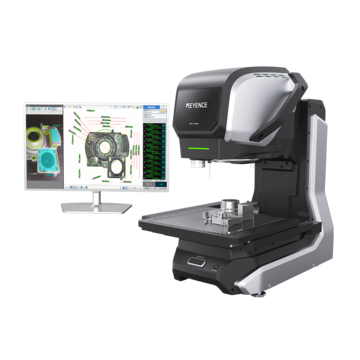
Automakers across their supply chains use GD&T. For the pistons to travel properly, engine blocks must have precise bore placement. Perpendicularity controls are necessary for gear alignment in transmission housings. Complex GD&T verification across a variety of component types is handled by the XM Series. Before they become expensive recalls, quality teams identify deviations. While preserving production speed, this proactive strategy lowers scrap and safeguards brand reputation.
True position measurement advantages become clear when dealing with pattern locations. For structural stability, the bolt circles must line up precisely. For electrical continuity, connector pins must be precisely spaced. Quality assurance is no longer a bottleneck but rather a competitive advantage thanks to modern measurement tools that assess these standards in seconds as opposed to hours.
Optimize Your GD&T Inspections with KEYENCE Solutions
Request a demo and discover how our systems can streamline your GD&T processes.

Frequently Asked Questions
What is the difference between GD&T and traditional measurement methods?
Traditional methods measure simple dimensions like length and width, while GD&T defines how features relate to each other and function within assemblies, providing complete geometric control.
How can KEYENCE systems help with GD&T compliance?
KEYENCE measurement systems automatically calculate geometric tolerances, generate automatic inspection reports , and verify compliance against specifications without complex programming requirements.
What are the key challenges in implementing GD&T?
Training teams to read and interpret symbols correctly takes time, and establishing proper datum schemes requires careful planning based on functional requirements.
How does GD&T improve the manufacturing process?
It reduces interpretation errors between design and production teams, focuses inspection efforts on functionally critical features, and enables global collaboration with standardized communication.
Related Products
Related Downloads
-

XM Series Handheld Probe Coordinate Measuring Machine Catalog
Brochure for the XM-5000 Series Handheld CMM. Portable CMM to easily and accurately measure 3D and GD&T features anywhere including the shop floor and in the machine tool.
-
WM-6000 series Wide Area CMM Catalog
Brochure for the WM-6000 series Wide-Area CMM. A portable setup with a wireless handheld probe that enables users measure large parts and equipment.